Brother International LK3-B432E MKII Instruction Manual - English - Page 16
. Installing the control box, with the screws
 |
View all Brother International LK3-B432E MKII manuals
Add to My Manuals
Save this manual to your list of manuals |
Page 16 highlights
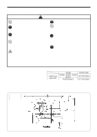
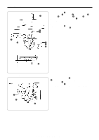
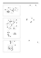
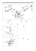
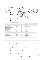
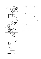
3-4 . Installing the control box LK3-B430E Mark II LK3-B432E Mark II LK3-B433E Mark II !0 !1 !2 w 3. INSTALLATION r t y u i o 3mm Table tCushions yCushion collars u Rubber collers i Flat washers o Nuts e q [LK3-B431E Mark II] r !3 !2 !0 !1 t y u i o w e q 1. Remove the 12 screws q, and then open the covers (panel mounting assembly w and main P.C. board mounting plate e). NOTE: When opening the cover, hold it securely so that it does not fall down. 2. Install the control box with the four accessory bolts r, cushions t, cushion collars y, rubber collars u, flat washers i and nuts o as shown in the illustration above. At this time, leave a gap of approximately 3 mm between the work table and the top of the box. * Use two nuts o at each installation location, and make sure that both nuts are tightened. 3. Close the covers (panel mounting assembly w and main P.C. board mounting plate e), and tighten them with the screws q. * The main P.C. board mounting plate e will be opened again during "3-13. Connecting the cords", so provisionally tighten it with the screw q. 4. Install the power switch !0 with the two screws !1. 5. Secure the power switch cord with the three staples !2. 6. Pass the motor cord through the cord hole !3. LK3-B430E-, B431E-, B432E-, B433E- Mark II 10
-
 1
1 -
2
-
3
-
4
-
5
-
6
-
7
-
8
-
9
-
10
-
 11
11 -
 12
12 -
 13
13 -
 14
14 -
 15
15 -
 16
16 -
 17
17 -
 18
18 -
 19
19 -
 20
20 -
 21
21 -
22
-
23
-
24
-
25
-
26
-
27
-
28
-
29
-
30
-
31
-
32
-
33
-
34
-
35
-
36
-
37
-
38
-
39
-
40
-
41
-
42
-
43
-
44
-
45
-
46
-
47
-
48
-
49
-
50
-
51
-
52
-
53
-
54
-
55
-
56
-
57
-
58
-
59
-
60
-
61
-
62
-
63
-
64
-
65
-
66
-
67
-
68
-
69
-
70
-
71
-
72
-
73
 |
 |
