Brother International MD-817 Service Manual
Brother International MD-817 Manual
 |
View all Brother International MD-817 manuals
Add to My Manuals
Save this manual to your list of manuals |
Brother International MD-817 manual content summary:
- Brother International MD-817 | Service Manual - Page 1
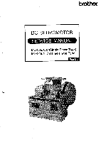
DC SERVOMOTOR SERVICE MANUAL MD-806, 807 (Single-Phase Type) MD-816, 817 (Three-Phase Type) Mark II - Brother International MD-817 | Service Manual - Page 2
- Brother International MD-817 | Service Manual - Page 3
manual describes the motor and the control box and also covers adj- ustments. Read the service manual LIST 11 OPERATION PANEL 12 OPERATION INSTRUCTIONS Motor control and control box use TROUBLESHOOTING GUIDE 41 CONTROL BOX TROUBLESHOOTING GUIDE OUTL INE 50 CONTROL BOX TROUBLESHOOTING GUIDE - Brother International MD-817 | Service Manual - Page 4
a D pr inted -ci rcuit board 58 Treadle un i t 67 TIMING CHART 73 BLOCK DIAGRAM OF CONTROL CIRCUIT 74 DETAILS OF CONNECTOR PANEL 75 SEWI NG MACHI NE CONTROL SYSTEM BLOCK DIAGRAM 16 MOTOR CONTROL SYSTEM BLOCK DIAGRAM 77 CONTROL BOARD CIRCU IT DIAGRAM 78 SPARE PARTS CODE NUMBER OF - Brother International MD-817 | Service Manual - Page 5
C DESCRIPTION OF THE MOTOR * The Brother DC servomotor is best suited to reducing sewing labor requirements and enhancing automation; the advanced functions being provided with a total system design. FEATURES 1. Energy Savings Power consumption is reduced about 50% with the DC servomotor when - Brother International MD-817 | Service Manual - Page 6
SPECIFICATIONS The operation panel is optionally available. Use the operation panel which is best suited to your work. *Operation panel E-20 ti -20 O D41 u7 AA, •4 i,4, 'Pad a • E. Fr •-- .44 7°1 I E-40 _ . dit Itnt C°] ggiAg . -1 E-100 EXEDRA #aaa ®gin-. 6-1012 EU=/ X FAT 2,moro - Brother International MD-817 | Service Manual - Page 7
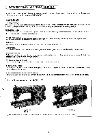
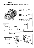
C NAME OF EACH PARTS 8 7 6 16 tt 4: 1 2 3 4 5 9 tt 10 11 12 0 Stator (magnet) 0 Rotor CD Brake coi l ( l ining) Brake armature Pul ley Reactor 0 Brush holder Thermistor Sewing machine plug 10 Presser foot l ifter plug 11 Brake plug 12 Synchronizer plug 9 Slow start switch 14 Correction - Brother International MD-817 | Service Manual - Page 8
Motor Mounting Template 66 80 56 --1 20 4)25 R10 4)42 R10 15±0.1 0 1110 " 3-4)8.5 CI" LC, .-I - Brother International MD-817 | Service Manual - Page 9
( PRINCIPLE OF CONTROL SYSTEM ) 0 O 0000 00O0 0 0 00 III 0 1. When the power switch 0 is turned on and the treadle is depressed, the start signal and a voltage corresponding to how 0 far the treadle is depressed, are supplied to the control box by the treadle unit. The voltage is supplied to - Brother International MD-817 | Service Manual - Page 10
CONFIGURATION trd et& W o PLQ P Bea& Synchronizer 01/03mm Source DC. Servo motor Fuse Treadle Power supply Full-wave rectification -ass circuit Protective circuit Power transistor POWER CIRCUIT UNIT _.J Transformer r Power supply circuit 4, Power ON-OFF detection L 1 Motor drive - Brother International MD-817 | Service Manual - Page 11
(MD-806, 816, 807, 817 SPARE PARTS CODE NUMBERS OF MOTORS ) motor assembly bracket R bracket L brush rotor Frame assemb I y#2 Brake stator phase voltage 1 .cp 110V 220V 230V 240V 34) 220V 380V 415V 1,34) al l 14) al l 34) 220V 34) 380V 415V 1, 3 4) al I 14) al l 34) 220V 34) - Brother International MD-817 | Service Manual - Page 12
Explanation of the control box's name plate name pl ate brother DC MOTOR MD-816-m THREE PHASE 415V CONTROL BOX TYPE GOEDIZI]fEinG1 No. C)C)0 XXXXX BROTHER INDUSTRIES,. LTD. MADE IN JAPAN 0: month ©: year C): modi f ication No. MD -8X6-Ill D a 20 l•'7 M 09 use treadl e pul ley outer sewing - Brother International MD-817 | Service Manual - Page 13
Spare parts list 1 MKII 6738.8842 etc. NBN B730 BAST LS2-8883 CO V FD4 or FD4 group control circuit board (BPD600) 1phase(1 0) 110V 1phase (i co ) 220-240V S-PCB-MK2-11106 J80090-001 S-PCB-MK2-1240B J80091-001 S-PCB-NBN-1110B J80095-001 S-PCB-NBN-12408 J80096-001 S-PCB-BAST11108 J80100-001 - Brother International MD-817 | Service Manual - Page 14
Snare parts list 2 PCB. name sewing machine 87380 1470C -A 81910 B7740 #450D181[3[30 #490C- #450D- 88450 843Z.025 B438027 BAS-102 BPD100 ET. FO BPD5_83 8845-900S BPD500 APM BPD500 ABL, SBL control circuit board 1phase(1 0) 110V 1phase(1 0) . 220-240V 291788-001 3phase(30) 220-240V - Brother International MD-817 | Service Manual - Page 15
*1 Sensor Sewing machine B737 MK2 B748 8842 group 6791 8774 6798 S I (white type) S II (white type) SENS0R#1-1 (291655-011) SENS0R#2-2 (291657-01 1) #2-1 (291659-01 1) #1-3 (291673-011) #2-3 (291674-011) #1-4 (291656-011) #2-4 (291640-01 1) #1-5 (291658-01 1) #2-5 (291641-01 1) #1-6 ( - Brother International MD-817 | Service Manual - Page 16
C OPERATION PANEL -) Sewing machine Model B737Markll - Brother International MD-817 | Service Manual - Page 17
OPERATION INSTRUCTIONS Motor control and control box use 88 * , bCal lull ,..i. , 0 00 0 * The power lamp will light up when the power switch 0 is turned on. * Sewing speed - Brother International MD-817 | Service Manual - Page 18
ADJUSTMENT :; M DC Servomotor Rotating direction of machine O About 13mm * Lower the machine head and then mount the belt on the motor pulley and the ma- chine pulley. * The belt fits the machine pulley and the motor pulley as shipped. However, the belt tension may loosen in time; check the belt - Brother International MD-817 | Service Manual - Page 19
Synchronizer Model DB2-B737 •B748 .B774 .B791 0 Higher Lower Il I® Needle up stop 0.5mm Thin, regular materials: 10-12mm Thick materials: 10-14mm Needle down stop Reference line 18-22mm * The synchronizer detects the needle position with two sensors. The thread trimming signal is timed to the - Brother International MD-817 | Service Manual - Page 20
Motor brake Cork brake 0 00 0.2 mm Window for adjusting the brake lining gap 0 Aussparung zur PrOfung des BreMsbelagabstands Fenetre pour le reglage du jeu de garniture de (rein Ventanilla pare ajuste de la separation del forro de frenos 0.1 mm a 0.15 mm O O 0.3 mm * Check for brake lining wear ( - Brother International MD-817 | Service Manual - Page 21
11 Brush replacement Val 0 1. Be sure to turn off the power switch. 2. Disconnect the motor plug. 3. Remove the clamp screws 0. 4. Remove the brushes 0. 5. After checking the reference line of the brush a mount the usable brush 0 so that the reference line points toward the treadle unit. Replace - Brother International MD-817 | Service Manual - Page 22
Control box Control box (Model DB2-B737) The high speed dial, backtack stitch dial, power lamp, needle position switch, one-stitch modification switch, starting slowly switch and connector for synchronizer are arranged on the front of the control box. All these parts are already provided on the - Brother International MD-817 | Service Manual - Page 23
El Function of the toggle switches ,. , SW1 ,, ( left side ) SW2 ( center ) MK II stopping position correcti on by up or down actuator switch NBN t t SW3 ( ri ght side ) slow start thread nipper BAST t t slow start COV t spreader thread trimming EJ Function of the slide - Brother International MD-817 | Service Manual - Page 24
E] Explanation each DIP switches of Mark II, NBN, BAST DIPA 1 Position of presser after ON thread trimming OFF Position of presser after ON 2 thread trimming with tree- die in neutral position OFF Position of presser when ON 3 machine is stopped with t- readle in neutral position OFF 4 - Brother International MD-817 | Service Manual - Page 25
Explanation DIP switch DIPC & DIPD of Mark II DIPC 1 Sewing machine ON speci₹ication (change on and off OFF timming of reverse solenoid at back- ON 2 tack) OFF Delay time from ON 3 presser down to * start OFF ON 4 Slowdown control OFF Continuous backta- ON 5 ck selection OFF ABCD+10 - Brother International MD-817 | Service Manual - Page 26
Explanation DIP switch DIPC & DIPD of NBN DIPC 1 ON OFF *1 ON *1 OFF *1 ON *1 Tension re lease OFF OFF setting at the 0 10 20 30 start of sewing ON 2 - OFF OFF ON ON OFF 3 Condense mode ON Condense mode (sett ing by needle number) OFF none 4 Slowdown control ON Normal ly - Brother International MD-817 | Service Manual - Page 27
Explanation DIP switch DIPC & DIPD of BAST DIPC 4 Slowdown control ON Normal ly slowdown (usual slowdown) OFF Fix time of inching period on slowdown DIPD 1 Mode selection ON Parameter setting mode OFF Normal ly sewing mode :Other DIP switches of DIPC,D are al l unused. - 23 - - Brother International MD-817 | Service Manual - Page 28
Explanation DIP switch of COV DIPA 1 Position of press- ON er after thread t- rimming OFF Down Raised Position of press- ON 2 er after thread t- rimming wi th trea- OFF dle in neutral po- sition Ra ised Down Position of press- ON 3 er when machine is stopped with trea- OFF dle at neutral - Brother International MD-817 | Service Manual - Page 29
Function of half 6 depressing the treadle backward 1 Reserved 8 Reserved Presser foot l ifter rise by half depressing the ON treadle backward OFF none Normal ly OFF Normal ly OFF DIPC 4 Slowdown control ON Normal ly slowdown (usual slowdown) OFF Fix time of inching period on slowdown DIPD 1 - Brother International MD-817 | Service Manual - Page 30
10 Parameter setting Start Set DIPD-1 to ON. • Turn off all LEDs. (When using 100 specification panel, display pattern 1.) • Stop thread trimming. • Press the thread trimming key two times quickly. (LED on the th ead trimming key blinks and parameter No. appears below A and B.) • Select paramete - Brother International MD-817 | Service Manual - Page 31
E Parameter and timing list 1. MK II specification Parameter No. 00 Default 00 Data setting range 00 - 03 Function The specifications of the machine head can be only temporarily changed. (Restoration to original state is made by DIPC 1 and 2.) 00: B737 etc. 01: B791 02: B774 03: B842 group 10 - Brother International MD-817 | Service Manual - Page 32
MKII and BAST Timing chart when the thread is trimmed Depressing treadle forward Depressing treadle backward Needle down position signal Needle up position signal Thread trimming solenoid Brake solenoid Wiper solenoid 40msec. T20 T21 Presser foot l ifter solenoid Motor Presser foot l ifter - Brother International MD-817 | Service Manual - Page 33
2. NBN specification Parameter No. 10 (T10) 11 (T11) Default Data setting range 15 00 - 25 (x10) (150 msec.) (0 - 250 msec.) 10 05 - 25 (x10) (100 msec.) (50 - 250 msec.) 12 (T12) 06 05 - 25 (x10) (60 msec.) (50 - 250 msec.) 13 (T13) 14 (T14) 30 10 - 90 (x10) (300 msec.) (100 - 900 - Brother International MD-817 | Service Manual - Page 34
NBN timing chart A. Thread trimming timing when SW 3 is set to ON ( when thread nipper function is activated ) Depressing treadle backward Needle down position signal Needle up position signal Pitch condense solenoid Thread trimming solenoid Tension release solenoid Brake solenoid Thread release - Brother International MD-817 | Service Manual - Page 35
3. BAST specification Parameter No. 11 (T11) Default Data setting range 04 03 -- 10 (x10) (40 msec.) (30 - 100 msec.) 13 (T13) 14 (T14) 30 (300 msec.) 36 (3 minutes) 10 -90 (x10) (100 - 900 msec.) 00 - 60 (x5) . (5 seconds - 5 minutes) 20 (T20) 02 01 -07 (x10) (20 msec.) (10 - 70 msec.) - Brother International MD-817 | Service Manual - Page 36
4. COV specification timing chart A. Time that folder opens and closes A. 1 Alternate motion ( when DIPA-7 is set to ON ) Folder switch for opening and closing folder ON ON ON OFF OFF OFF Folder opening and closing solenoid ---] ON ON OFF A. 2 Momentary motion ( when DIPA-7 is set to OFF - Brother International MD-817 | Service Manual - Page 37
TROUBLESHOOTING * When troubleshooting quality of the detailed parts (semiconductors) for mainten- ance. Trouble 1. The machine will not run even when stepping on the connector of the motor.) The machine pulley is too stiff to turn manually. [The machine or the motor (brake lining) is locked. - Brother International MD-817 | Service Manual - Page 38
Error Indication List Indication Error content The power LED blinks at a cycle of approx. 0.25 second. The buzzer sounds at a cycle of approx. 0.25 second. Machine motor lock. Higher voltage than usual is applied to the power. Needle up signal or needle down signal is not detected for three - Brother International MD-817 | Service Manual - Page 39
CHECKING THE MOTOR 1 Motor Motor M Approx. 1.2 ohm Torque thermister Black Blac Blue 6 3 5 2 Coil Approx. 0.3 ohm 4 Red Yellow Black Yellow Revolution thermister 1. Remove the motor cord (6P connector) from the connector part of the control box. 2. Measure with a tester set in the - Brother International MD-817 | Service Manual - Page 40
CHECKING THE MACHINE SOLENOIDS M Solenoid load of the machine Connector from the machine head Reverse switch 9 ® GND ® 8 5 0 Reverse solenoid Thread wiper solenoid Thread trimming solenoid (B737) Presser foot lift connecter Solenoid = GND 4 6 Presser foot lift switch 1. Remove the - Brother International MD-817 | Service Manual - Page 41
Ei Solenoids Table ( driving transistor No. & O ) control PCB spec. MK II NBN BAST C0V solenoid brake solenoid transistor No. --__ _ -- resistance of sol.( O ) trimmer solenoid transistor No. resistance of sol. ( O ) TR1 5.3 TR2 TR3 6.7 6.0 wiper solenoid transistor No. . - Brother International MD-817 | Service Manual - Page 42
, the machine speeds up. (Remark): Turn VR first to the left and then make speed adjustment from a lower speed, thereby Inside dial 0 avoiding troubles due to abnormal speed. d) Turn the power switch on and keep the treadle fully down when adjusting the speed. 2) Adjustment of end backtacking - Brother International MD-817 | Service Manual - Page 43
El Sewing speed of each machine Model No. & Spec B737-1 -3 -5 B747-5 B748-7 B798 B852 B853 B854 B791-3 -5 B774 B842-3 -5 B845 B847 B848 6730-1 -3 LS2-6883 FD4- 627X FD3-B25X High Speed 4,000 5,000 3,500 3,500 2,500 2,000 4,500 4,500 4,500 4,500 3,500 4,500 4,000 3,500 3,000 4,000 3,000 4,000 5,000 - Brother International MD-817 | Service Manual - Page 44
C NOTES REGARDING DC MOTOR INSTALLATION (1) Be sure, when using a three-phase power supply, to check the connection of the power plug. Be careful not to use a single-phase power supply. Even if a single-phase is used, there may be no abnormal condition. Note, however, that quick repeated starting - Brother International MD-817 | Service Manual - Page 45
C DC MOTOR TROUBLESHOOTING GUIDE Start Press the treadle slightly forward. Set the control box switches: • Needle position-needle (low- er) • Correction-none • Slow start-none • Set the maximum speed - Brother International MD-817 | Service Manual - Page 46
Depress the treadle to the rear. Depress the treadle forward. Does the machine operate at low speed? Yes Does the thread trimmer function? Yes Does the needle (upper) stop? Yes Repeat the forward and backward treadle depression steps. Is there any variation in the needle Yes (upper) stopping - Brother International MD-817 | Service Manual - Page 47
5 Is high-speed sewing possible? Yes Set the treadle to neutral. Depress the treadle backward. Is end backtacking possible? Yes Is the stitch count correct? Yes After completion of end backtacking, do the thread trimmer, thread wipe and needle (upper stop? Yes Set the treadle to neutral. Set the - Brother International MD-817 | Service Manual - Page 48
After depressing the treadle, return to neutral and stop the machine. Switch ON the actuator switch. Is one-stitch correction sewing possible? Yes Switch OFF the correction switch (control box). Depress the treadle backward. Switch ON the slow start switch (control box). Set the speed-adjustment - Brother International MD-817 | Service Manual - Page 49
. Replace the control box. #3 No operation box • Does the operation box lamp is illuminated. function correctly? (YES) Bulb failure-no functional problem. (NO) Malfunction of the operation Replace the operation box. box. • Other than that above. Malfunction of the control Replace the control - Brother International MD-817 | Service Manual - Page 50
ITEM PROBLEM #8 Needle (lower) doesn't stop. #9 Needle (lower) stops at different places. CHECK PROBABLE CAUSE REMEDY • Is the synchronizer OK? (NO) (YES) Synchronizer installation position is not - Brother International MD-817 | Service Manual - Page 51
ITEM PROBLEM #14 Needle (upper) stops at different places. #15 The stop position of the needle (upper) is not correct. #16 Thread wiper doesn't function. #17 Thread - Brother International MD-817 | Service Manual - Page 52
ITEM PROBLEM CHECK PROBABLE CAUSE REMEDY #19 Start backtacking is impossible. Malfunction of the control Replace the control box. printed-circuit board. #20 Will not perform • Is - Brother International MD-817 | Service Manual - Page 53
ITEM PROBLEM CHECK #33 Needle (upper) will not stop (control box). #34 Speed is not in accordance with the setting of the speed adjustment control. Note: Resistance - Brother International MD-817 | Service Manual - Page 54
CONTROL BOX TROUBLESHOOTING GUIDE OUTLINE PROBLEM 1. Motor won't operate. Lamp does not illuminate when power is ON. (Fuse has blown.) 2. Motor won't operate. Lamp illuminates when power is ON. 3. Machine abnormal - Brother International MD-817 | Service Manual - Page 55
C CONTROL BOX TROUBLESHOOTING GUIDE DETAILS ') (1) For other than the control box, it is particularly important to use products of confirmed good quality. (2) Do not use an extension cord for - Brother International MD-817 | Service Manual - Page 56
LI Main flow-chart START I Blown fuse A Motor starts when power switch turns ON. Disconnect (from among the external connectors) the power-supply, motor, brake, presser foot, thread trimmer and three stand-operation connectors. From among the internal connectors, disconnect CN5 from the D - Brother International MD-817 | Service Manual - Page 57
Caution (p.63) 1. Connect all connectors except the operation box. 2. Three printed-circuit board switches: needle position switch: lower; correction switch: OFF; slow-start switch: OFF. 3. Turn the high-speed VR fully counterclockwise. Related Connectors (p.55) Wiper operation with power ON. - Brother International MD-817 | Service Manual - Page 58
High-speed rotational irregularities. Speed reduction brake doesn't function. Continuous rotation at low speed. Needle (upper) doesn stop. V Starting rotation at slow speed. NO #107-1 YES Good low-speed range. NO #107-1 YES Rotation corresponds NO to treadle depression. #107-3 YES - Brother International MD-817 | Service Manual - Page 59
El Connector related • Fuse failure (#2, #3-7) • LED 1 illumination (#3) • LED 1 flashing (#5) Thread trimmer connector CN3 O g I I I I I I I ,0 Presser foot connector / Brake connector LED 1 (#3) O CD CN8 CN5 CN7 CN4 CN10 0 \ 0 0 8A fuse CN6 O Power-supply connector Motor connector,-- - Brother International MD-817 | Service Manual - Page 60
LED 1 NO illumination #3 More than 5V 5V OUT: OK #3-1 Less than 5V Dispose of printed-circuit board. YES Power OFF. CPU RUN: NO OK #3-2 YES YES Replace LED 1 or IC3 5V OUT 0S2 #3-5 NO NO 5V IN: OK #3-4 YES CN6 voltage: OK NO #3-6 YES Fuse failure NO #3-7 (p.55) YES Transformer - Brother International MD-817 | Service Manual - Page 61
2 CPU RUN: OK START CPU pin 27: OK NO #3-2A YES CPU pin 57: OK NO #3-2B YES CPU RUN: OK END Replace IC7. Replace the CPU (IC1) or HIC2 #3-2A CPU pin 27 (reset) +4.5V or more OV 30-40 msec. al- V Power on #3-2B CPU pin 57 (brake out) +4.5V or more OV V Power on 40 or 300 msec. 40 msec.: with - Brother International MD-817 | Service Manual - Page 62
D printed-circuit board (Don't touch PCB while LED is illuminated.) D printed-circuit board 1-110V assembly 1-240 V assembly 0 D printed-circuit board check D printed-circuit board 3-240V assembly 3-415V assembly D printed-circuit board check 0 Check 0 OTI D PCB 3 D-PCB 1-240V -C R2 I (9'4r - Brother International MD-817 | Service Manual - Page 63
LED 1 flashing #5 More than 15V NO Dispose of printed-circuit board. YES ±15V OUT: OK #5-1 YES NO Less than 15V Disconnect CN3. #5-2 15V OUT: OK #5-1 YES NO Power OFF Replace HIC5. CN3 connection ±15V OUT: 0O #5-3 YES Dispose of printed-circuit board. NO ±15V IN: OK #5-4 YES +15V NG - Brother International MD-817 | Service Manual - Page 64
D107 „K" or CN5 pin 2: OK #7 More than 15V NO Dispose of printed-circuit board. NO ±15V OUT: OK #7-1 YES D106 X: OK #7-4 NO PH52 pin 1: OK #7-5 NO (P61) NO Less than 15V Power OFF YES Dispose of printed-circuit board. YES ±15 V IN: 0O #7-3 NO ±15V IN: OK #7-2 YES +15V, NG Replace REG101. -15V: - Brother International MD-817 | Service Manual - Page 65
CP3: OK #7-6 YES CP6: OK #7-7 NO CP4: OK #7-8 NO PH1B pin 6: OK #7-9 NO V (P62) NO Replace HIC6. YES Replace HIC6. YES Replace HIC6 or IC301. YES Replace HIC5. 1 &(P52) #6 CP5: OK OBV: Check pin OBV (CP2) With HIGH VR fully clockwise: Treadle neutral: OV Treadle fully forward: 9.0V or more #6 ( - Brother International MD-817 | Service Manual - Page 66
V HIC2 pin 15: OK #7-10 NO CPU pin 51: OK #7-11 NO CPU RUN: OK #7-12 YES YES YES Replace HIC2. NO ZD1 "K": OK #7-16 NO Replace ZD1. YES Replace HIC2. CPU pin 38:OK #7-14 YES CPU pin 39: OK #7-15 YES Replace the CPU. NO NO HIC1 pin 16: OK #7-18 YES Replace HIC1. Replace the CPU or HIC2. HIC1 - Brother International MD-817 | Service Manual - Page 67
Caution C.) C.) _____ T net • 929 4 * •• ESEi bbb • • • , a.xa r TR2 TR5 TR5 T RI q' -*-eO5. • -. O .tr=,,, ▪ -2 I4ol4m •40 it, 04 54 -.4n910.0.4.2,,, ' "2 " : RE rei be P, bi -.1 ar " 111 ..tiStif p lgeaal . COE 1 Ina C p as Oil at MT/ - Lm--1 8 Mil rta BPD600-5 IBA? 0 - - Brother International MD-817 | Service Manual - Page 68
Wiper operates. YES #100 TR 3B: OK #100-1 NO CPU pin 61: OK #100-2 N NO CPU RUN: OK #100-3 YES Thread YES trimmer operates. #101 YES Replace TR3. YES Replace HIC2. TR 2B: OK #101-1 NO CPU pin 60: OK #101-2 NO NO CPU RUN: OK #101-3 YES YES Replace TF12. YES Replace HIC2. Replace - Brother International MD-817 | Service Manual - Page 69
Reverser operates. YES #102 TR 5B: OK #102-1 NO CPU pin 58: OK #102-2 NO N CPU RUN: OK #102-3 YES Brake sound is heard. NO #103 YES Replace TRS. YES Replace HIC2. 8A fuse: OK #103-1 YES TR 1B: OK #103-2 NO CPU RUN: OK #103-3 NO NO Replace the 8A fuse. YES Replace TR1. YES Replace the - Brother International MD-817 | Service Manual - Page 70
Operate at high speed #104 YES Motor 6-pin connector OK #104-1 YES Replace HIC5 & HIC6 NO Motor 6-pin connector repair 0 (P53) NO Low-speed torque: OK #106 Low-speed torque: OK YE #106-1 NO Replace HIC5 & HIC6 #104-1 related O Oi 000D DOC OHO / Check this connections is correct. (P53) # - Brother International MD-817 | Service Manual - Page 71
Treadle unit Phot Int & VC chart 9.2 4000 t CP5 (VC) V SPM 2.2 1000 } 0.5 215 } -8 is -2 0 2 FRONT L H level 4.5V or more REAR L PRESSER H DOWN Trim Pres. up Neutral Pres. down 141 12 .5 1I6 STROKE (mm)-0- L level 0.5V or less Low sp Top Variable sp. sp. Adjustments Shutter - Brother International MD-817 | Service Manual - Page 72
itiewystV HA 4000 -SPM VR1 ADJUSTMENT 3000- VR1 left 2000- VR1 ' right 1000- 2150 4000 SPM 2 15 VR3 ADJUSTMENT 3000- 12 VR3 right i 16 mm V193 left 4000 SPM VR2 ADJUSTMENT 3000- 2000- 1000- 215 0 4000 SPM 2 5 VR4 ADJUSTMENT ----------- VR2 right „ V192 left 12 30 16 mm VR4 - Brother International MD-817 | Service Manual - Page 73
Deceleration NO brake functions. #108 CPU pin 25: OK NO #108-1 YES Replace HIC6. Replace HIC3. (P53) 4REG1 „,„ 73-'1 r'iroat i 0. 01'; et -", Hi i IIMIII *-*. JCI - OIS 36 'lg."! -,-,,-,--7--.--_-.,,L 1.-. L- CR(Pr /I 14 24# El; ZO2E. gt,20i; 8. MA r " 11 • • a r - Brother International MD-817 | Service Manual - Page 74
Machine stops. NO #109 Stop position: OK NO #110 Low-speed is good. NO #109-1 YES CPU pin 17: OK #109-2 YES Adjust VR TRIM, INCH. NO Replace the CPU Replace HIC1. Low-speed is good. NO #110-1 YES Adjust VR TRIM, INCH. Replace HIC3. P> (P53) #109-1, #110-1 (VR TRIM, INCH) (P53) - Brother International MD-817 | Service Manual - Page 75
Machine operates. NO #111 CPU pin 38: OK #111-1 YES YES Replace the CPU. CPU pin 39: OK #111-2 YES CPU pin 18: OK #111-3 NO Replace HIC1. NO NO HIC1 pin 16: OK #111-5 YES Replace HIC1. H1C1 pin 11: OK #111-4 YES NO NO Treadle unit (p.67) Replace HIC1. (P53) (CPU-38) #111-2 (CPU-39) ( - Brother International MD-817 | Service Manual - Page 76
Wiper operates. NO #113 YES TR 3B: OK #113-1 Thread NO trimmer operates. #112 TR 2B: OK #112- 1 YES NO Replace TR3. NO Replace TR2. CPU pin 61: OK #113-2 NO Replace the CPU. YES Replace HIC2. CPU pin 60: OK #112-2 NO Replace the CPU. D (P53) YES Replace HIC2. D (P53) Needle (lower - Brother International MD-817 | Service Manual - Page 77
El Needle (lower) stop Machine (spm) FRONT SW H CPU-39 (0V) L REAR SW CPU-38 (OV) L PEDAL SENSOR CP5 (OBV) BRAKE ON H CPU-34 (OV) L BRAKE OFF L H CPU-16 (OV) L NEEDLE DOWN H CPU-17 (OV) L BRAKE CPU-57 (0V) L LOW SP H CPU-51 (OV) L - VR TRIM or INCH Adjust speed VR1 Adjust speed 60MSeC. Needle ( - Brother International MD-817 | Service Manual - Page 78
BLOCK DIAGRAM OF CONTROL CIRCUIT 7.40 MD-806(1 PHASE) REV. SOL. -816(3 PHASE) 5. on W IP. SOL TRIM. SOL. e 6. 7n PRE. SOL. 9. 5n EARTH 'EARTH KNEE SW. BRAKE SOL. 5. 30 2 TREADLE UNI 1e4/C,ND) CNI C:f1:1-1 i )(.2) : 20 : :1 a GREEN YE9LL re3i IA )qq,E CNC OS® 000 CNE 00 • 0 - Brother International MD-817 | Service Manual - Page 79
C DETAILS OF CONNECTOR PANEL Model 0B2-B737etc. 00) Machine head 12P connector Release power Release output Presser foot l ifter 6P connector Presser power Presser Input Brake 2P connector Brake Power Brake output 52 3 GND Option 4 Thread trimming power Presser output Thread trimming output - Brother International MD-817 | Service Manual - Page 80
SEWING MACHINE CONTROL SYSTEM BLOCK DIAGRAM MD-806, 816 Pedal Front SW Rear SW Actuator SW Presser SW Synchronizer DN UP E NC. NO sync Trans former CN6 +35V h12V Power Supply 5V + OV 12P Hic 1 6P INP Circuit CN9 Hic 3 ENC CONT 5) CP7 Motor Lock Protect Machine Brake Timing '.$ Y2 - Brother International MD-817 | Service Manual - Page 81
MOTOR CONTROL SYSTEM BLOCK DIAGRAM 4P Fuse Source AC.3o Fuse Earth -.• T H CN4 if' BD SCR PTR C E 6P 4 5 C Base OCV TH 2 3 TH 6 D printed-circuit board 2 3 4 56 OBV if if Vf Vf if' Transformer Power supply CN Power supply +15V 050 15V +15V 0100V 15V if CP6 1AP CP3 •-•00 M +15V - Brother International MD-817 | Service Manual - Page 82
V >10010 age& wean IMO 1011 Ile AV AO 0 • • gill AO M. MO 6 AN 13 • N101 • N1/w1 IP NM I 011 13 1004 And -ma " 4,,„„ 11001A0 •1111.11 az AO YON IN t • Nat I • g MA -• OW"g 7717 en 00? O1S Dinni eiNgs guist 110 Id Il i rC t lId MOM • - WON SIP 111 or et Me - Brother International MD-817 | Service Manual - Page 83
BPD600 - KY ICNn 1190 SOU ROOD Ka IOMM =Was POO 0._s aft JUNO 0/00 U WOO • 4- urn ! 0•01 40. 020i 04.M0 PIP OPP vas sow S. OPO -w 010) 'CPO Cr, as 0040. 1304 4.4 Oa ae'OM. NP 1029 La 0 01M 011. 1 ft .. 'Ii , 0 I 1C301 MN3 ii 4t, asa APO 11107r4 M la as masa 0.1 IMMO WOWS - Brother International MD-817 | Service Manual - Page 84
MD-806, 816 spare parts code number of PCB 1, TAO .2ba OOO * * **.P TR2 TR6 I 820 I~r 1 eduDO rt i ..* 4 TR1. - GCE _;„.,-R . rA.- •(D.; -;T O 0O 0" 9 F1 REG1 9c CV a IGO m m..'r 0,2 T T „ *. **O0 eep ii 1.,g4:12 ' -mg! JCI-WS "e, 85 Ztu 0,1 WM) A F 111 1KN 2.1, c OS - Brother International MD-817 | Service Manual - Page 85
MD-806, 816 spare parts code number of PCB (BPD600-X) SYMBOL IC1 IC2 IC3 IC4, 5 IC6 IC7, 8, 102.202 IC9 IC101, 201 IC301 IC302 CODE NAME *1 J00246001 091100006 091100004 091100151 U33544000 091100006 J00247001 J00248001 831198001 *1 LSIM6M80041P BIPIC74LSO6 BIPICI4LSO4 RIP IC74LSI51 B IP - Brother International MD-817 | Service Manual - Page 86
MD-806, 816 spare parts code number of PCB (BPD600-X) code numbers of common parts SYMBOL CODE NAME NOTE SPEC. Mark II NBN BAST ZD5 U32725000 7DRD5. 1JSB1 none O none ZD2 233280001 ZDAU01-08 O O O ZD4 230814001 11)11033 O O O ZD53, 54, 55. 301 U32269000 ZDRD20JSB1 O O O - Brother International MD-817 | Service Manual - Page 87
MD-806, 816 spare parts code number of PCB (BPD600-X) SYMBOL CODE NAME NOTE SPEC. Mark if 1 NBN , BAST R19, 26, 27, 30, 38. 42 090242520 DR-A14AJ242S 2. 4K 1/4W O O O 47. 48, 49, 50, 220 R33 090272620 DR-A14AJ272S 2.7K 1/4W O O O R210, 326, 329, 331 090392620 DR-A14AJ392S 3. - Brother International MD-817 | Service Manual - Page 88
MD-806, 816 spare parts code number of PCB (BPD600-X) code numbers of common parts SYMBOL CODE NAME NOTE SPEC. C13 C8 C109 C302 FIN3 FIN1.2 Markll BBB Y51024200 P-CAPCITOR40081020. 0010 400V C) C) Y51040040 P-CAPCITOR50B104 0. 1u 50V C) C) Y52220010 P-CAPCITOR50B222 0.0022u 50V () () - Brother International MD-817 | Service Manual - Page 89
MD-806,816 TREADLE UNIT(PS-PCB#11 ASSM.) RI R3 4 C C2 V13.3 R9 03 VR1 Z01 %FE Fia HO C 7 R5 5 •2 P11 vrizs R7 2 R4 00V RIO 2 C IVR R12 R13 14 • TR3 02 TRI TR2I PI5V C3 3 C 2 0.4V C4 NI5V • +14 (E1V) PRESSER 9 DONN FRONT REAR OV •=4 _1=50 4 C pi2.E::30 E .11. 0 O 0 Dee 5 - Brother International MD-817 | Service Manual - Page 90
D printed-circuit board 1-110V-C assembly 11R0-C TR2.1- 0 TRM-CE 0 OLET OL R9 RIO ACK MG FB( OS CR 5 7 C8 _I _I 4 -64O8 5 -VV\r- 0 MOLEX STRAIN P L E 2907 • ° 000120 0 TOM- E OLD GR PI PI 5VMEOL NAME PA D POL 4 R40941 0 CODE 0' 228372001 NOTE 4000. 111F ~ca ACn Ore. POT - Brother International MD-817 | Service Manual - Page 91
D printed-circuit board 1-120V-C assembly TEIM- C O 11/16-8 TRM- CE O OR.I.DL:19iiA)6 ORANGE . ERA ORANGE [ R2 BD 8 BLACK) - GREEN E8 GSA GI GR. SR 8 CS 0 MOLEX STRAIN RELIEF 298T BROWN TRM- E SYMBOL C 1 Ca NAME CAPACITOR. POLYEBTER400A105 CAPAC I TOR POLyESTER6300104 CS. R. 7.8 RI .. - Brother International MD-817 | Service Manual - Page 92
D printed-circuit board 1-240V-C assembly TI154-C 74M-0 TIM-Ct 0 ORANGE rito22 VIOLET svA F 0415601 VIREO] DVS St0NITE.01 ACIO 41542111TE I BLACK) 419 •(RED, NOV C2 F5(SA) SA • ORANGE 42 ORAviii __SLANGS too TE Coo ! I CA 03 eo 09 410 L Ds z fT IRO CSCSCI CS -1 _1 P"S -vvv" •- - Brother International MD-817 | Service Manual - Page 93
D printed-circuit board 3-240V-C assembly CmA AIRED) WHITE 1 2(VRITE 001 IRO CI CO FBISA IL ACA S TIBLACX 6 2 I - GREEN 0 • TI BLAcil iSIRED/ ZR3 NOV OSA FcI2A) CO C4 CS 0(GREEN) GREEN TRW-C TRIS-8 ORANGE MNI TE TAM-CE VIOLET OR GE 'IQRA GE JP C7 Rib R23 .,. . CI.2 VR 117 " T T CIS CIO - Brother International MD-817 | Service Manual - Page 94
D printed-circuit board 3-415V-C assembly „., 0 TRW GC OR ORANGE • I OLET WHITE SUNNITE CI Ca CN CB OP RI BI5 OLUEI BLUE D -PCB 2-415V -C 62 NB EE C3 01 CC 6(GREEN) EN CI 14 CII C13 R24 MOLEX STRAIN RELIEF 5298T YMBOL NAME Gt.CU.E.CT CAPAGE TOR. POLYESTER10006101 ce. CIA C4. CZ. - Brother International MD-817 | Service Manual - Page 95
OP Printed-circuit board E20 CNE 0243 E2 SENSOR DA EYG ET] DIGITS DIGITS 5 DIGITS OiGiT3 GAS 13 c c .044 D2 ZY O MM. la CNS 50 o- Iv c 21 LE00014 5V OV SOLED° DA SEG 0 S SEG I 9 SEG 2 10 SEG 3u SEGOFF 12 042 azta 3C4SaiS SIELELIO POWER LED 20 Cv PLED ¶ ry CI e o, RP nAa RA3 R 35 ov - Brother International MD-817 | Service Manual - Page 96
OP Printed-circuit board E40 C1,12. 0713 SWLEDi 14 E2 3 SENSOR 2 A KEYS 13 KEYS 16 XEY2 17 2S PA6 osv 00V NACia.A.,0A3 015170 ♦ O10171 110172 a O10113 14 2 13 J ., 2 12 0 3 6 bow 10 9 IS 3 16 13 5 • 2 11 110 00 5254 09 OA °A5 SEG O 10 SEG I a SEG 2 666 3 11 SEGOff 12 OA6zaaa7 - Brother International MD-817 | Service Manual - Page 97
C TIMING CHART OF OPERATION PANEL E-40 f. >3 2msEC DIGIT 0 DIGIT 1 DIGIT 2 I 1 DIGIT 3 IC1-1(0) "A" . B. IC1-2 (1) - IC1-3 (2) 1- 1. C IC1-4 (3) i ' D IC1-5 (4) 1 IC1-6 (5) lt IC1-7 (6) IC1-9 (7) IC1-10 (8) SEGOFF I i i I SW SW3 9N6 SN9 12 /4, 5 7. 8 71-0, 1i SW15 /1-6-.--17 EACH - Brother International MD-817 | Service Manual - Page 98
OP Printed-circuit board E100 5112. 033 055110 T1 DIGITS 012123 "IT44 '4+4;44,- • 424,44 4-+4- '3 2' SEG 0 e SEG 0 9 SEG 2 s SEG 3 1 SES0F£ ss 5..200 OA 711 c4S",", RAZ 50-3 42 IS S- 55 i5 5c n 10 o dw 44 03 9 CC) ) SN zo 5V 0v 792 J541 Pic oov DOM E-100 2,Trir SM (2J a 8 3 .o - Brother International MD-817 | Service Manual - Page 99
CB/ COO El 5EN50 0070 15 KEY1 16 KEY; 17 OEGITO DEGIT1 000112 0 00011'3 alb 14 A V 0. 6. RA2. RA5 SEGO a SEG1 a 200210 5EG311 SEGOFF iz r GI a Bi 52 c 11 L6 i Ay I - - --1 W a 0 2 ra---mT----a-n 415161 DA6 0A2 ov SOLE 00 SwLED1 POWER LEG IV R2 PLED 0 1 8022E 14 51 1 T N-20 O - Brother International MD-817 | Service Manual - Page 100
CR El SENSOR DAS KENO KEY1 NEY2 OEGITO OEGITO (LEGIT OEG/T 00 08 DV TRI OS CIE RAI Al •3 11 SEGO SEG1 SEG2 SEIGS SEGOFF MOO 008 02 DA2 Go SWLE00 SWLEDI PGWER LED CI 0 BlIZZE 00 PLE02 1316/ IA NI N-40 14111 IMP! SMIDI /FY ON OP Printed-circuit board N40 SYMBOL D41.043. 1345 042.044 - Brother International MD-817 | Service Manual - Page 101
CN .CM3 El SENSOR KEYS KEYI KEYS DEGITO 4 OEGIT1 5 DEGIT2 I OEGI T3 ON ON 24. 2 3 6 3 4 5 7 5 10 11 41 IC 14 08 a v0 ov oA SEGO 0 SEW. GEG2 10 SEG3 11 SEGOFFI2 SY/LEDO/3 SWLE0114 5 OV I BUZZER. POWER LEO 20 --MC 2 N ca N oov a r -AM r.A" - 5f 04 •a12rII-m M„N, -' e ,101--ANH 00 - Brother International MD-817 | Service Manual - Page 102
SENSOR Printed-circuit board S1 CN2 El 3 5V 1 OV 11 POWER 12 LED 5V Di 0 Vi 50 V Rif R3 C1 201 OV o 5V C2 o OV R2 V02 7 sal T C3 R61 Rw 5 : I TRi 2 1 RA7nr 0 OV OV R22 O V1 k R8 C4 R10 " -- il AM R1 w11 2 8 1C2 3 4 VR lec- 1 5 ► 6 iC2 0 OV Ri33 R15 8V V2 "1 12 5V PLED 6 V2 - Brother International MD-817 | Service Manual - Page 103
SENSOR Printed-circuit board S2 ,C4 140741S14 1 0 HBSENSORCOAD# 1 C 4 7, NRT _ R5 III M IIi II pia -AL- 5 EM " TTRI ± I161, 1' ,C3 : 12V .00 RI2 II le ,,3 • rs. CN2 01 El /\J\\...9.s2v .1OV 5v R3 7 i400US 150US 5v V_ - HBSENSORCOAD#2 SENSOR ON a:. I 102" Leos) i z - Rte se # - Brother International MD-817 | Service Manual - Page 104
( HIC CIRCUIT DIAGRAM ) M INP CIRCUIT (228307001) +5V IN +5V 8 OV OUT Pin No (IN-OUT) IN OUT IN 2 3 11 4 5 13 6 7 16 9 10 18 OUT 12 14 15 17 IN OUT 19 20 22 21 24 23 25 26 2 OUT DRIVE (228308001) +5V 17 O 18 zs T +5V 2 3, 6, 9, 11, 13 15 O 19, 21, 23 25 O 27, 29 O 8 + - Brother International MD-817 | Service Manual - Page 105
a ENC CONT (228309001) OUT -• 8V power supply 2 O 36 INA OUT •>ais) a INB +5V +5V R24 47K • C8 I 0 1,uF Q 10 ---O CP7 11 0 +5V 8b 1 O- 7J, OV D PR Q C CL 0 One-shot timer 70ms 12 70ms 13 MOTOR DRV (228310001) 7 6 +15V 3 0 -15V OV - 101 - - Brother International MD-817 | Service Manual - Page 106
E MOTOR INST (228311001) 26 24 19 20 18 21 5 22 17 +15V 27 25 23 TRiM (LOW) SBL SBT EBT 15 13 14 12 AMP COM +5V -5V AMP AMP 16 10 -15V 0 MOTOR CONT (228312001) +15V 5o O aO 120 77 I O -15V 13o iR22o,LHvR 1...;L 16 0--- 19 18 15 AMP R332(SVR) 17 O MO- AMP - Brother International MD-817 | Service Manual - Page 107
FRAME ASSEMBLY #2 REPLACEMENT Refer to the motor disassembly diagram (Fig. 1). Up Disassembly (1) Remove the two MD carbon brushes 1. Note: The position of each carbon brush should be noted. (2) Remove the screw 55 and the belt cover 54. (3) Remove the nut 53. and then remove the pul ley 50 and the - Brother International MD-817 | Service Manual - Page 108
0 Assembly (1) Pass the cable of the new frame assembly through bracket assembly L. When doing so, note the following. 1) Be careful that the cable is not caught in the frame. 2) Be sure to align the bracket's rib with the space of the upper magnet in the frame. Bracket Assembly L Cable Frame - Brother International MD-817 | Service Manual - Page 109
(6) Temporarily secure the brake stator assembly to bracket R using a screw. (7) Insert the washer and sunk key on the rotor shaft, and then insert the brake armature assembly. (8) Align of the brake stator. Clearance Brake Stator Brake Armature 6 Armature Stopper Adjust the position of the - Brother International MD-817 | Service Manual - Page 110
(12) Pass all through the new tube. If, rather than a new tube, the plate tube used before is used as is, the following method is easy. Tube Suitable cord Wrap with tape (13) Pass all plug pins through the plug cover and insert at the 6-pin plug's designated position. Red Blue Black (two) Black - Brother International MD-817 | Service Manual - Page 111
- Brother International MD-817 | Service Manual - Page 112
BROTHER INDUSTRIES, LTD. NAGOYA, JAPAN Printed in Japan, 1992, 12 J90003-001
-
 1
1 -
 2
2 -
 3
3 -
 4
4 -
 5
5 -
 6
6 -
 7
7 -
8
-
9
-
10
-
11
-
12
-
13
-
14
-
15
-
16
-
17
-
18
-
19
-
20
-
21
-
22
-
23
-
24
-
25
-
26
-
27
-
28
-
29
-
30
-
31
-
32
-
33
-
34
-
35
-
36
-
37
-
38
-
39
-
40
-
41
-
42
-
43
-
44
-
45
-
46
-
47
-
48
-
49
-
50
-
51
-
52
-
53
-
54
-
55
-
56
-
57
-
58
-
59
-
60
-
61
-
62
-
63
-
64
-
65
-
66
-
67
-
68
-
69
-
70
-
71
-
72
-
73
-
74
-
75
-
76
-
77
-
78
-
79
-
80
-
81
-
82
-
83
-
84
-
85
-
86
-
87
-
88
-
89
-
90
-
91
-
92
-
93
-
94
-
95
-
96
-
97
-
98
-
99
-
100
-
101
-
102
-
103
-
104
-
105
-
106
-
107
-
108
-
109
-
110
-
111
-
112
 |
 |
DC
SERVOMOTOR
SERVICE
MANUAL
MD
-806,
807
(Single
-Phase
Type)
MD
-816,
817
(Three
-Phase
Type)
Mark
II