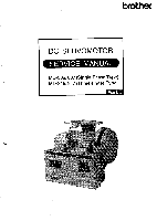
Brother International MD-817 Service Manual - Page 3
Brother International MD-817 Manual
 |
View all Brother International MD-817 manuals
Add to My Manuals
Save this manual to your list of manuals |
Page 3 highlights
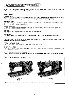
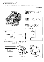
INTRODUCTION This servi ce manual is compi led for the technical staff responsible for maintai- ni ng and inspecting the drive motor designed for the automat ic thread trimming machine. The manual describes the motor and the control box and also covers adj- ustments. Read the service manual careful ly so that you understand the right ha- nding and adjustment. TABLE OF CONTENTS DESCRIPTION OF THE MOTOR 1 SPECIFICATIONS 2 NAME OF EACH PARTS 3 PRINCIPLE OF CONTROL SYSTEM 5 CONFIGURATION 6 MD-806.816.807. 817 SPARE PARTS CODE NUMBERS OF MOTORS 7 Spare parts code for control box 8 Spare parts I i st1 9 Spare parts l ist2 10 Sensor. CPU&ROM LIST 11 OPERATION PANEL 12 OPERATION INSTRUCTIONS Motor control and control box use 13 ADJUSTMENT 011 DC Servomotor 14 aD Need l e pos ition detector 14 0 Motor 16 Eg Brush replacement 17 5] Checking AC low vol tage output 17 53 Control box 18 09 Function of the toggle swi tches 19 11 Funct ion of the sl ide switches 19 Eg Explanat ion each DIP swi tches of MarkI I.NBN, BAST 20 El Parameter setti ng 26 03 Parameter and timing l ist 27 TROUBLESHOOTING 33 Error indication l ist 34 CHECKING THE MOTOR Cl] Motor 35 E5 Brake 35 CHECKING THE MACHINE SOLENOIDS ED So l enoi d load of the machine 36 al Solenoi ds table 37 SPEED ADJUSTMENT FOR EACH MACHINE ail Selection of motor pul ley and method of replacemant 38 D Adjustment of each speed 38 (7.-5 Sewing speed of each mac ine 39 NOTES REGARDING DC MOTOR INSTALLATION 40 DC MOTOR TROUBLESHOOTING GUIDE 41 CONTROL BOX TROUBLESHOOTING GUIDE OUTL INE 50 CONTROL BOX TROUBLESHOOTING GUIDE DETAILS 51 III Mai n f low -chart 52 En Connector related 55
-
 1
1 -
 2
2 -
 3
3 -
 4
4 -
 5
5 -
 6
6 -
 7
7 -
 8
8 -
 9
9 -
10
-
11
-
12
-
13
-
14
-
15
-
16
-
17
-
18
-
19
-
20
-
21
-
22
-
23
-
24
-
25
-
26
-
27
-
28
-
29
-
30
-
31
-
32
-
33
-
34
-
35
-
36
-
37
-
38
-
39
-
40
-
41
-
42
-
43
-
44
-
45
-
46
-
47
-
48
-
49
-
50
-
51
-
52
-
53
-
54
-
55
-
56
-
57
-
58
-
59
-
60
-
61
-
62
-
63
-
64
-
65
-
66
-
67
-
68
-
69
-
70
-
71
-
72
-
73
-
74
-
75
-
76
-
77
-
78
-
79
-
80
-
81
-
82
-
83
-
84
-
85
-
86
-
87
-
88
-
89
-
90
-
91
-
92
-
93
-
94
-
95
-
96
-
97
-
98
-
99
-
100
-
101
-
102
-
103
-
104
-
105
-
106
-
107
-
108
-
109
-
110
-
111
-
112
 |
 |
