Brother International MD-817 Service Manual - Page 9
Principle, Control, System
 |
View all Brother International MD-817 manuals
Add to My Manuals
Save this manual to your list of manuals |
Page 9 highlights
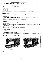
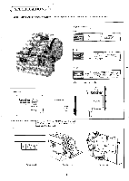
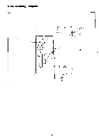
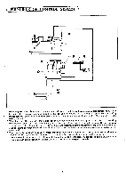
( PRINCIPLE OF CONTROL SYSTEM ) 0 O 0000 00O0 0 0 00 III 0 1. When the power switch 0 is turned on and the treadle is depressed, the start signal and a voltage corresponding to how 0 far the treadle is depressed, are supplied to the control box by the treadle unit. The voltage is supplied to the motor 0 by the control circuit board in the control box 0 so that the motor runs in proportion to the depression of the treadle to drive the sewing machine. 0 2. When the treadle is returned to the neutral position (with foot taken off), the neutral signal is sent to the control box 0 by the treadle unit 0 and the brake command is given by the control circuit board to decelerate the motor 0. Then the signal from the synchronizer 0, mounted on the pulley of the sewing machine, is sent to the control box 0 and the brakes are ap- plied so that the operation of the sewing machine is stopped with the needle in the down stopping position set by the syn- chronizer 0. 3. When the treadle is stepped on again, the thread trimming signal is sent to the control box 0 by the treadle unit 0 and the command is given by the control circuit board to run the motor 0 at the thread trimming speed (inching speed). Then the signal from the synchronizer 0 is sent to the control box 0 and the brakes 0 are applied so that the operation of the sewing machine is stopped with the needle in the up position set by the synchronizer G.
-
 1
1 -
2
-
3
-
 4
4 -
 5
5 -
 6
6 -
 7
7 -
 8
8 -
 9
9 -
 10
10 -
 11
11 -
 12
12 -
 13
13 -
 14
14 -
15
-
16
-
17
-
18
-
19
-
20
-
21
-
22
-
23
-
24
-
25
-
26
-
27
-
28
-
29
-
30
-
31
-
32
-
33
-
34
-
35
-
36
-
37
-
38
-
39
-
40
-
41
-
42
-
43
-
44
-
45
-
46
-
47
-
48
-
49
-
50
-
51
-
52
-
53
-
54
-
55
-
56
-
57
-
58
-
59
-
60
-
61
-
62
-
63
-
64
-
65
-
66
-
67
-
68
-
69
-
70
-
71
-
72
-
73
-
74
-
75
-
76
-
77
-
78
-
79
-
80
-
81
-
82
-
83
-
84
-
85
-
86
-
87
-
88
-
89
-
90
-
91
-
92
-
93
-
94
-
95
-
96
-
97
-
98
-
99
-
100
-
101
-
102
-
103
-
104
-
105
-
106
-
107
-
108
-
109
-
110
-
111
-
112
 |
 |
