Cisco 3725 Software Configuration Guide - Page 132
Linking PBX Users with E&M Trunk Lines
 |
UPC - 746320810911
View all Cisco 3725 manuals
Add to My Manuals
Save this manual to your list of manuals |
Page 132 highlights
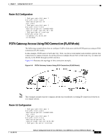
Chapter 4 Configuring Voice-over-IP destination-pattern +4155264000 port 1/0/0 ! Create voip dial-peer 20 dial-peer voice 20 voip !Define its associated telephone number and IP address destination-pattern +4085264000 sess-target ipv4:10.0.0.1 ! Configure serial interface 0/0 interface Serial0/0 ip address 40.0.0.1 255.0.0.0 no ip mroute-cache ! Configure RTP header compression ip rtp header-compression ip rtp compression-connections 25 ! Enable RSVP on this interface ip rsvp bandwidth 96 96 fair-queue 64 256 3 clockrate 64000 ! Configure IGRP router igrp 888 network 10.0.0.0 network 20.0.0.0 network 40.0.0.0 Linking PBX Users with E&M Trunk Lines The following example shows how to configure VoIP to link PBX users with E&M trunk lines. In this example, a company wants to connect two offices: one in San Jose, California and the other in Salt Lake City, Utah. Each office has an internal telephone network using PBX, connected to the voice network by an E&M interface. Both the Salt Lake City and the San Jose offices are using E&M Port Type II, with four-wire operation and ImmediateStart signaling. Each E&M interface connects to the router using two voice interface connections. Users in San Jose dial "8-569" and then the extension number to reach a destination in Salt Lake City. Users in Salt Lake City dial "4-527" and then the extension number to reach a destination in San Jose. Figure 4-2 illustrates the topology of this connection example. Figure 4-2 Linking PBX Users with E&M Trunk Lines Example Note This example assumes that the company already has established a working IP connection between its two remote offices. Software Configuration Guide for Cisco 2600 Series, Cisco 3600 Series, and Cisco 3700 Series Routers 4-6 OL-1957-04
-
 1
1 -
2
-
3
-
4
-
5
-
6
-
7
-
8
-
9
-
10
-
11
-
12
-
13
-
14
-
15
-
16
-
17
-
18
-
19
-
20
-
21
-
22
-
23
-
24
-
25
-
26
-
27
-
28
-
29
-
30
-
31
-
32
-
33
-
34
-
35
-
36
-
37
-
38
-
39
-
40
-
41
-
42
-
43
-
44
-
45
-
46
-
47
-
48
-
49
-
50
-
51
-
52
-
53
-
54
-
55
-
56
-
57
-
58
-
59
-
60
-
61
-
62
-
63
-
64
-
65
-
66
-
67
-
68
-
69
-
70
-
71
-
72
-
73
-
74
-
75
-
76
-
77
-
78
-
79
-
80
-
81
-
82
-
83
-
84
-
85
-
86
-
87
-
88
-
89
-
90
-
91
-
92
-
93
-
94
-
95
-
96
-
97
-
98
-
99
-
100
-
101
-
102
-
103
-
104
-
105
-
106
-
107
-
108
-
109
-
110
-
111
-
112
-
113
-
114
-
115
-
116
-
117
-
118
-
119
-
120
-
121
-
122
-
123
-
124
-
125
-
126
-
 127
127 -
 128
128 -
 129
129 -
 130
130 -
 131
131 -
 132
132 -
 133
133 -
 134
134 -
 135
135 -
 136
136 -
 137
137 -
138
-
139
-
140
-
141
-
142
-
143
-
144
-
145
-
146
-
147
-
148
-
149
-
150
-
151
-
152
-
153
-
154
-
155
-
156
-
157
-
158
-
159
-
160
-
161
-
162
-
163
-
164
-
165
-
166
-
167
-
168
-
169
-
170
-
171
-
172
-
173
-
174
-
175
-
176
-
177
-
178
-
179
-
180
-
181
-
182
-
183
-
184
-
185
-
186
-
187
-
188
-
189
-
190
-
191
-
192
-
193
-
194
-
195
-
196
 |
 |
