Cisco 3725 Software Configuration Guide - Page 134
PSTN Gateway Access Using FXO Connection
 |
UPC - 746320810911
View all Cisco 3725 manuals
Add to My Manuals
Save this manual to your list of manuals |
Page 134 highlights
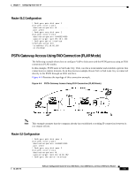
Chapter 4 Configuring Voice-over-IP Note PBXs should be configured to pass all DTMF signals to the router. Cisco recommends that you do not configure "store-and-forward" tone. Note If you change the gain or the telephony port, make sure that the telephony port still accepts DTMF signals. PSTN Gateway Access Using FXO Connection The following example shows how to configure VoIP to link users with the PSTN gateway using an FXO connection. In this example, users connected to Router SJ in San Jose, California can reach PSTN users in Salt Lake City, Utah via Router SLC. Router SLC in Salt Lake City is connected directly to the PSTN through an FXO interface. Figure 4-3 illustrates the topology of this connection example. Figure 4-3 PSTN Gateway Access Using FXO Connection Example Note This example assumes that the company already has established a working IP connection between its two remote offices. Router SJ Configuration ! Configure pots dial-peer 1 dial-peer voice 1 pots destination-pattern +14085274000 port 1/0/0 ! Configure voip dial-peer 2 dial-peer voice 2 voip destination-pattern +9........... session target ipv4:172.16.65.182 ! Configure the serial interface interface serial 0/0 clock rate 2000000 ip address 172.16.1.123 no shutdown Software Configuration Guide for Cisco 2600 Series, Cisco 3600 Series, and Cisco 3700 Series Routers 4-8 OL-1957-04
-
 1
1 -
2
-
3
-
4
-
5
-
6
-
7
-
8
-
9
-
10
-
11
-
12
-
13
-
14
-
15
-
16
-
17
-
18
-
19
-
20
-
21
-
22
-
23
-
24
-
25
-
26
-
27
-
28
-
29
-
30
-
31
-
32
-
33
-
34
-
35
-
36
-
37
-
38
-
39
-
40
-
41
-
42
-
43
-
44
-
45
-
46
-
47
-
48
-
49
-
50
-
51
-
52
-
53
-
54
-
55
-
56
-
57
-
58
-
59
-
60
-
61
-
62
-
63
-
64
-
65
-
66
-
67
-
68
-
69
-
70
-
71
-
72
-
73
-
74
-
75
-
76
-
77
-
78
-
79
-
80
-
81
-
82
-
83
-
84
-
85
-
86
-
87
-
88
-
89
-
90
-
91
-
92
-
93
-
94
-
95
-
96
-
97
-
98
-
99
-
100
-
101
-
102
-
103
-
104
-
105
-
106
-
107
-
108
-
109
-
110
-
111
-
112
-
113
-
114
-
115
-
116
-
117
-
118
-
119
-
120
-
121
-
122
-
123
-
124
-
125
-
126
-
127
-
128
-
 129
129 -
 130
130 -
 131
131 -
 132
132 -
 133
133 -
 134
134 -
 135
135 -
 136
136 -
 137
137 -
 138
138 -
 139
139 -
140
-
141
-
142
-
143
-
144
-
145
-
146
-
147
-
148
-
149
-
150
-
151
-
152
-
153
-
154
-
155
-
156
-
157
-
158
-
159
-
160
-
161
-
162
-
163
-
164
-
165
-
166
-
167
-
168
-
169
-
170
-
171
-
172
-
173
-
174
-
175
-
176
-
177
-
178
-
179
-
180
-
181
-
182
-
183
-
184
-
185
-
186
-
187
-
188
-
189
-
190
-
191
-
192
-
193
-
194
-
195
-
196
 |
 |
