Cisco AIR-LAP1131G-A-K9 Hardware Installation Guide - Page 30
Access Point Layout and Connectors, LEDs
 |
View all Cisco AIR-LAP1131G-A-K9 manuals
Add to My Manuals
Save this manual to your list of manuals |
Page 30 highlights
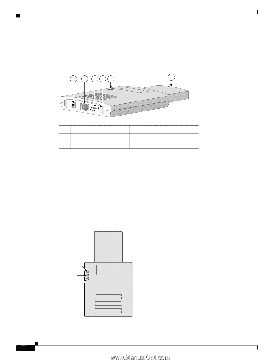
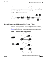
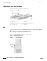
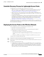
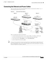
Basic Installation Guidelines Access Point Layout and Connectors Figure 2-1 shows the access point layout and connectors. Figure 2-1 Access Point Layout and Connectors 1 2 345 6 Chapter 2 Installing the Access Point 81180 LEDs 1 48-VDC power port 2 Ethernet port (RJ-45) 3 Cable lock slot 4 Mode button 5 Status LEDs 6 Antenna The three LEDs on the top of the access point report Ethernet activity, association status, and radio activity. • The Ethernet LED signals Ethernet traffic on the wired LAN. • The status LED signals operational status. • The radio LED signals wireless traffic over the radio interface. Figure 2-2 shows the three status LEDs. Figure 2-2 Access Point LEDs Ethernet Status Radio 81597 Cisco Aironet 1100 Series Access Point Hardware Installation Guide 2-4 OL-4309-07
-
 1
1 -
2
-
3
-
4
-
5
-
6
-
7
-
8
-
9
-
10
-
11
-
12
-
13
-
14
-
15
-
16
-
17
-
18
-
19
-
20
-
21
-
22
-
23
-
24
-
 25
25 -
 26
26 -
 27
27 -
 28
28 -
 29
29 -
 30
30 -
 31
31 -
 32
32 -
 33
33 -
 34
34 -
 35
35 -
36
-
37
-
38
-
39
-
40
-
41
-
42
-
43
-
44
-
45
-
46
-
47
-
48
-
49
-
50
-
51
-
52
-
53
-
54
-
55
-
56
-
57
-
58
-
59
-
60
-
61
-
62
-
63
-
64
-
65
-
66
-
67
-
68
-
69
-
70
-
71
-
72
-
73
-
74
-
75
-
76
-
77
-
78
-
79
-
80
-
81
-
82
-
83
-
84
-
85
-
86
-
87
-
88
-
89
-
90
-
91
-
92
-
93
-
94
-
95
-
96
-
97
-
98
-
99
-
100
-
101
-
102
-
103
-
104
-
105
-
106
-
107
-
108
-
109
-
110
-
111
-
112
-
113
-
114
-
115
-
116
 |
 |