Cisco AIR-LAP1131G-A-K9 Hardware Installation Guide - Page 54
Step 3, Caution, Inserting Radio Card in Mini-PCI Connector
 |
View all Cisco AIR-LAP1131G-A-K9 manuals
Add to My Manuals
Save this manual to your list of manuals |
Page 54 highlights
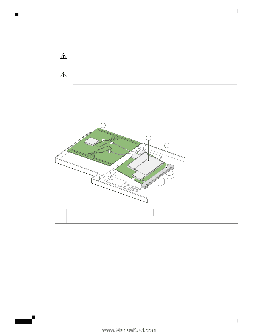
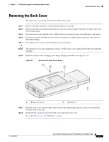
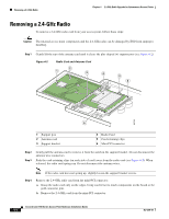
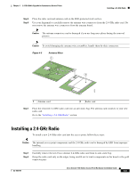
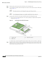
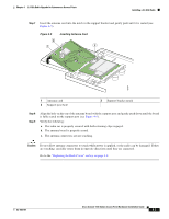
Installing a 2.4-GHz Radio Chapter 4 2.4-GHz Radio Upgrade for Autonomous Access Points Step 3 Step 4 Place the radio card on the anti-static work surface next to the antenna card. Use your fingers to carefully connect the antenna wire connectors to the connectors on the 2.4-GHz radio card (see Figure 4-3). Caution The antenna connectors can be damaged by using a pair of long-nose pliers. Caution To avoid damaging the antenna wire assemblies, handle them by their connectors. Step 5 Insert the radio card into the access point's mini-PCI connector by following these steps: a. Tilt the radio card at approximately 20o to 30o so that its gold pins are aligned with the mini-PCI connector (see Figure 4-4). Figure 4-4 Inserting Radio Card in Mini-PCI Connector 1 2 3 95753 1 Antenna card 2 Radio card 3 Mini-PCI connector Step 6 b. Push the radio card into the mini-PCI connector until it is fully seated (you will hear a slight snap). Hold the top of the antenna card with one hand and carefully push the radio card down with your other hand (towards the access point's motherboard) until the card-retaining clips lock into the notches on the side of the radio card (you will hear a click). Cisco Aironet 1100 Series Access Point Hardware Installation Guide 4-6 OL-4309-07
-
 1
1 -
2
-
3
-
4
-
5
-
6
-
7
-
8
-
9
-
10
-
11
-
12
-
13
-
14
-
15
-
16
-
17
-
18
-
19
-
20
-
21
-
22
-
23
-
24
-
25
-
26
-
27
-
28
-
29
-
30
-
31
-
32
-
33
-
34
-
35
-
36
-
37
-
38
-
39
-
40
-
41
-
42
-
43
-
44
-
45
-
46
-
47
-
48
-
 49
49 -
 50
50 -
 51
51 -
 52
52 -
 53
53 -
 54
54 -
 55
55 -
 56
56 -
 57
57 -
 58
58 -
 59
59 -
60
-
61
-
62
-
63
-
64
-
65
-
66
-
67
-
68
-
69
-
70
-
71
-
72
-
73
-
74
-
75
-
76
-
77
-
78
-
79
-
80
-
81
-
82
-
83
-
84
-
85
-
86
-
87
-
88
-
89
-
90
-
91
-
92
-
93
-
94
-
95
-
96
-
97
-
98
-
99
-
100
-
101
-
102
-
103
-
104
-
105
-
106
-
107
-
108
-
109
-
110
-
111
-
112
-
113
-
114
-
115
-
116
 |
 |