D-Link DGS-3208TG User Guide - Page 33
Q VLANs Spanning Multiple Switches, Example of typical VLAN configuration
 |
UPC - 790069239366
View all D-Link DGS-3208TG manuals
Add to My Manuals
Save this manual to your list of manuals |
Page 33 highlights
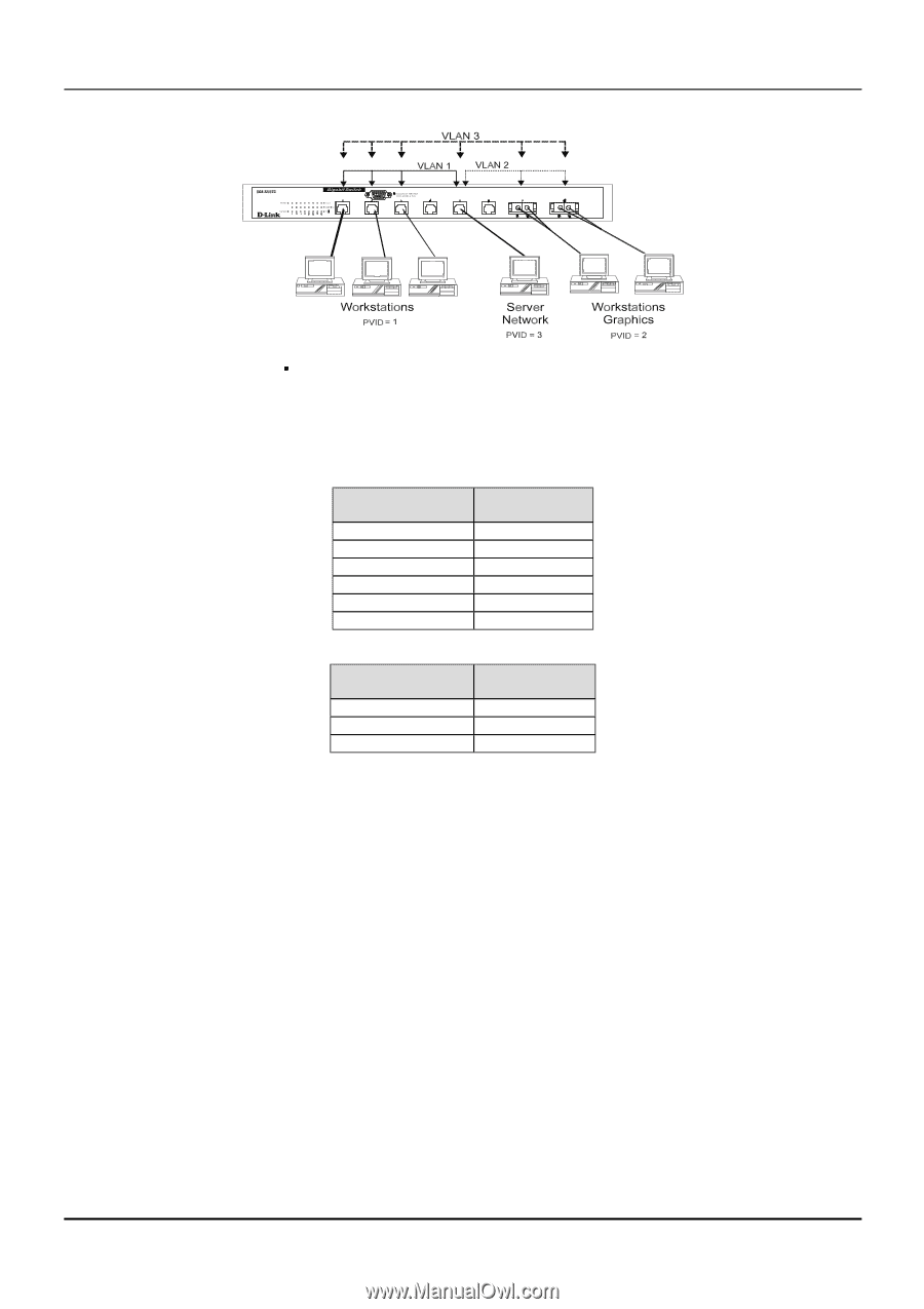
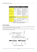
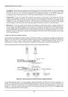
Gigabit Ethernet Switch User's Guide Figure 5-4. Example of typical VLAN configuration In the above example, there are three different 802.1Q VLANs and each port can transmit packets on one of them according to their Port VLAN ID (PVID). However, a port can receive packets on all VLANs (VID) that it belongs to. The assignments are as follows: PVID (Port VLAN ID) 1 1 1 2 2 3 Ports Port 1 Port 2 Port 3 Port 7 Port 8 Port 5 VID (VLAN ID) 1 2 3 Member Ports 1, 2, 3, 5 5, 7, 8 1, 2, 3, 5, 7, 8 Table 5-2. VLAN assignments for Figure 5-4 The server attached to Port 5 is shared by VLAN 1, VLAN 2, and VLAN 3 because Port 5 is a member of all three VLANs (it is listed as a member of VID 1, 2, and 3). Since it can receive packets from all three VLANs, all ports can successfully send packets to it to be printed. Ports 1, 2 and 3 send these packets on VLAN 1 (their PVID=1), and Ports 7 and 8 send these packets on VLAN 2 (PVID=2). The third VLAN (PVID=3) is used by the server to transmit files that had been requested on VLAN 1 or 2 back to the computers. All computers that use the server will receive transmissions from it since they are all located on ports which are members of VLAN 3 (VID=3). 802.1Q VLANs Spanning Multiple Switches 802.1Q VLANs can span multiple switches as well as your entire network. Two considerations to keep in mind while building VLANs of this sort are whether the switches are IEEE 802.1Q-compliant and whether VLAN packets should be tagged or untagged. Definitions of relevant terms are as follows: ♦ Tagging The act of putting 802.1Q VLAN information into the header of a packet. Ports with tagging enabled will put the VID number, priority, and other VLAN information into all packets that flow out it. If a packet has previously been tagged, the port will not alter the packet, thus keeping the VLAN information intact. Tagging is used to send packets from one 802.1Q-compliant device to another. 21
-
 1
1 -
2
-
3
-
4
-
5
-
6
-
7
-
8
-
9
-
10
-
11
-
12
-
13
-
14
-
15
-
16
-
17
-
18
-
19
-
20
-
21
-
22
-
23
-
24
-
25
-
26
-
27
-
 28
28 -
 29
29 -
 30
30 -
 31
31 -
 32
32 -
 33
33 -
 34
34 -
 35
35 -
 36
36 -
 37
37 -
 38
38 -
39
-
40
-
41
-
42
-
43
-
44
-
45
-
46
-
47
-
48
-
49
-
50
-
51
-
52
-
53
-
54
-
55
-
56
-
57
-
58
-
59
-
60
-
61
-
62
-
63
-
64
-
65
-
66
-
67
-
68
-
69
-
70
-
71
-
72
-
73
-
74
-
75
-
76
-
77
-
78
-
79
-
80
-
81
-
82
-
83
-
84
-
85
-
86
-
87
-
88
-
89
-
90
-
91
-
92
-
93
-
94
-
95
-
96
-
97
-
98
-
99
-
100
-
101
-
102
-
103
-
104
-
105
-
106
-
107
-
108
-
109
-
110
-
111
-
112
-
113
-
114
-
115
-
116
-
117
-
118
-
119
-
120
-
121
-
122
-
123
-
124
-
125
-
126
-
127
-
128
-
129
-
130
-
131
-
132
-
133
-
134
-
135
-
136
 |
 |