Dell GX240 User's Guide - Page 101
If the release lever on the socket is not fully extended, move it to
 |
UPC - 683728165390
View all Dell GX240 manuals
Add to My Manuals
Save this manual to your list of manuals |
Page 101 highlights
Microprocessor Installation 1 1 pin-1 corners of microprocessor and socket aligned NOTICE: You must position the microprocessor correctly in the socket to avoid permanent damage to the microprocessor and the computer when you turn on the computer. 3 If the release lever on the socket is not fully extended, move it to that position now. 4 With the pin-1 corners of the microprocessor and socket aligned, align the pins on the microprocessor with the holes in the socket. NOTICE: When you place the microprocessor in the socket, be sure that all of the pins go into the corresponding holes on all sides of the socket. Be careful not to bend the pins. Installing Upgrades 99
-
 1
1 -
2
-
3
-
4
-
5
-
6
-
7
-
8
-
9
-
10
-
11
-
12
-
13
-
14
-
15
-
16
-
17
-
18
-
19
-
20
-
21
-
22
-
23
-
24
-
25
-
26
-
27
-
28
-
29
-
30
-
31
-
32
-
33
-
34
-
35
-
36
-
37
-
38
-
39
-
40
-
41
-
42
-
43
-
44
-
45
-
46
-
47
-
48
-
49
-
50
-
51
-
52
-
53
-
54
-
55
-
56
-
57
-
58
-
59
-
60
-
61
-
62
-
63
-
64
-
65
-
66
-
67
-
68
-
69
-
70
-
71
-
72
-
73
-
74
-
75
-
76
-
77
-
78
-
79
-
80
-
81
-
82
-
83
-
84
-
85
-
86
-
87
-
88
-
89
-
90
-
91
-
92
-
93
-
94
-
95
-
 96
96 -
 97
97 -
 98
98 -
 99
99 -
 100
100 -
 101
101 -
 102
102 -
 103
103 -
 104
104 -
 105
105 -
 106
106 -
107
-
108
-
109
-
110
-
111
-
112
-
113
-
114
-
115
-
116
-
117
-
118
-
119
-
120
-
121
-
122
-
123
-
124
-
125
-
126
-
127
-
128
-
129
-
130
-
131
-
132
-
133
-
134
-
135
-
136
-
137
-
138
-
139
-
140
-
141
-
142
-
143
-
144
-
145
-
146
-
147
-
148
-
149
-
150
-
151
-
152
-
153
-
154
-
155
-
156
-
157
-
158
-
159
-
160
-
161
-
162
-
163
-
164
-
165
-
166
-
167
-
168
-
169
-
170
-
171
-
172
-
173
-
174
-
175
-
176
-
177
-
178
-
179
-
180
-
181
-
182
-
183
-
184
-
185
-
186
-
187
-
188
-
189
-
190
-
191
-
192
-
193
-
194
-
195
-
196
-
197
-
198
-
199
-
200
-
201
-
202
-
203
-
204
-
205
-
206
-
207
-
208
-
209
-
210
-
211
-
212
-
213
-
214
-
215
-
216
-
217
-
218
-
219
-
220
-
221
-
222
-
223
-
224
-
225
-
226
-
227
-
228
-
229
-
230
-
231
-
232
-
233
-
234
-
235
-
236
-
237
-
238
-
239
-
240
-
241
-
242
-
243
-
244
-
245
-
246
-
247
-
248
-
249
-
250
-
251
-
252
-
253
-
254
-
255
-
256
-
257
-
258
-
259
-
260
-
261
-
262
-
263
-
264
-
265
-
266
-
267
-
268
-
269
-
270
-
271
-
272
-
273
-
274
-
275
-
276
-
277
-
278
-
279
-
280
-
281
-
282
-
283
-
284
-
285
-
286
-
287
-
288
-
289
-
290
-
291
-
292
-
293
-
294
-
295
-
296
-
297
-
298
 |
 |

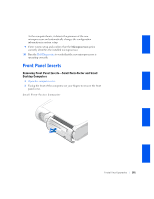
Installing Upgrades
99
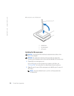
Microprocessor Installation
NOTICE:
You must position the microprocessor correctly in the socket to
avoid permanent damage to the microprocessor and the computer when you
turn on the computer.
3
If the release lever on the socket is not fully extended, move it to that
position now.
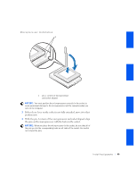
4
With the pin-1 corners of the microprocessor and socket aligned, align
the pins on the microprocessor with the holes in the socket.
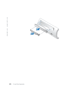
NOTICE:
When you place the microprocessor in the socket, be sure that all of
the pins go into the corresponding holes on all sides of the socket. Be careful
not to bend the pins.
1
pin-1 corners of microprocessor
and socket aligned
1