Dell GX240 User's Guide - Page 102
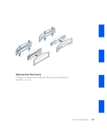
Replacing the Heat Sink or Heat-Sink/Blower Assembly
 |
UPC - 683728165390
View all Dell GX240 manuals
Add to My Manuals
Save this manual to your list of manuals |
Page 102 highlights
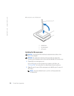
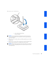
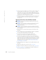
www.dell.com | support.dell.com 5 Set the microprocessor lightly in the socket and make sure all pins are headed into the correct holes. Because your computer uses a ZIF socket, there is no need to use force (which could bend the pins if the microprocessor is misaligned). When the microprocessor is positioned correctly, press it with minimal pressure to seat it. 6 When the microprocessor is fully seated in the socket, pivot the release lever back toward the socket until it snaps into place, securing the microprocessor. Replacing the Heat Sink or Heat-Sink/Blower Assembly NOTICE: Ground yourself by touching an unpainted metal surface on the back of the computer. NOTICE: If you are installing a microprocessor replacement kit from Dell, return the microprocessor to Dell in the same package in which your replacement kit was sent. NOTICE: If you are not installing a microprocessor upgrade kit from Dell, reuse the original blower/heat-sink assembly and securing clips when replacing the microprocessor. 1 Remove the film covering the thermal grease on the bottom of the heat sink. 2 On the small form-factor and small desktop computers, reinstall the two screws that attach the blower to the heat sink. 3 Lower the heat sink or blower/heat-sink assembly to the microprocessor so that the heat sink fits in the retention base. 4 For each of the replacement metal clips, fit the end of the clip that does not have the latch over its tab on the retention base. Then, fit the middle of the clip over the middle tab on the retention base, and press down on the clip's latch to secure the clip to the retention base (see the illustration for your computer in "Removing the Heat Sink or Heat-Sink/Blower Assembly"). 5 On the small mini-tower computer, lower the airflow shroud over the heat sink. 6 Plug the fan cable into its connector on the system board. 7 Plug the 12-volt power cable into its connector on the system board. 8 Close the computer cover, reconnect your computer and devices to their electrical outlets, and turn them on. 100 Installing Upgrades
-
 1
1 -
2
-
3
-
4
-
5
-
6
-
7
-
8
-
9
-
10
-
11
-
12
-
13
-
14
-
15
-
16
-
17
-
18
-
19
-
20
-
21
-
22
-
23
-
24
-
25
-
26
-
27
-
28
-
29
-
30
-
31
-
32
-
33
-
34
-
35
-
36
-
37
-
38
-
39
-
40
-
41
-
42
-
43
-
44
-
45
-
46
-
47
-
48
-
49
-
50
-
51
-
52
-
53
-
54
-
55
-
56
-
57
-
58
-
59
-
60
-
61
-
62
-
63
-
64
-
65
-
66
-
67
-
68
-
69
-
70
-
71
-
72
-
73
-
74
-
75
-
76
-
77
-
78
-
79
-
80
-
81
-
82
-
83
-
84
-
85
-
86
-
87
-
88
-
89
-
90
-
91
-
92
-
93
-
94
-
95
-
96
-
 97
97 -
 98
98 -
 99
99 -
 100
100 -
 101
101 -
 102
102 -
 103
103 -
 104
104 -
 105
105 -
 106
106 -
 107
107 -
108
-
109
-
110
-
111
-
112
-
113
-
114
-
115
-
116
-
117
-
118
-
119
-
120
-
121
-
122
-
123
-
124
-
125
-
126
-
127
-
128
-
129
-
130
-
131
-
132
-
133
-
134
-
135
-
136
-
137
-
138
-
139
-
140
-
141
-
142
-
143
-
144
-
145
-
146
-
147
-
148
-
149
-
150
-
151
-
152
-
153
-
154
-
155
-
156
-
157
-
158
-
159
-
160
-
161
-
162
-
163
-
164
-
165
-
166
-
167
-
168
-
169
-
170
-
171
-
172
-
173
-
174
-
175
-
176
-
177
-
178
-
179
-
180
-
181
-
182
-
183
-
184
-
185
-
186
-
187
-
188
-
189
-
190
-
191
-
192
-
193
-
194
-
195
-
196
-
197
-
198
-
199
-
200
-
201
-
202
-
203
-
204
-
205
-
206
-
207
-
208
-
209
-
210
-
211
-
212
-
213
-
214
-
215
-
216
-
217
-
218
-
219
-
220
-
221
-
222
-
223
-
224
-
225
-
226
-
227
-
228
-
229
-
230
-
231
-
232
-
233
-
234
-
235
-
236
-
237
-
238
-
239
-
240
-
241
-
242
-
243
-
244
-
245
-
246
-
247
-
248
-
249
-
250
-
251
-
252
-
253
-
254
-
255
-
256
-
257
-
258
-
259
-
260
-
261
-
262
-
263
-
264
-
265
-
266
-
267
-
268
-
269
-
270
-
271
-
272
-
273
-
274
-
275
-
276
-
277
-
278
-
279
-
280
-
281
-
282
-
283
-
284
-
285
-
286
-
287
-
288
-
289
-
290
-
291
-
292
-
293
-
294
-
295
-
296
-
297
-
298
 |
 |
