Dell GX280DT User Guide - Page 162
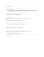
Attaching and Removing the Computer Stand
 |
UPC - 851846002006
View all Dell GX280DT manuals
Add to My Manuals
Save this manual to your list of manuals |
Page 162 highlights
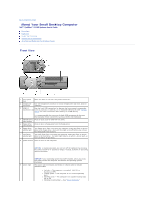
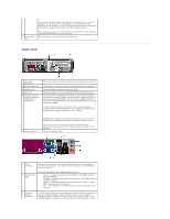
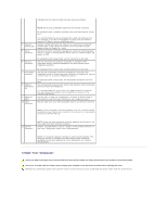
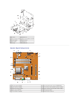
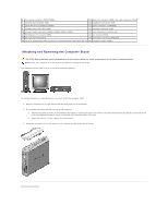
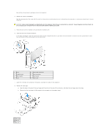
6 front-panel connector (FRONT PANEL) 19 serial port connector (SER1) and video connector (VGA) 7 CD/DVD drive connector (IDE) 20 parallel port connector (PAR) 8 serial ATA drive 0 connector (SATA0) 21 power connector (12VPOWER) 9 standby power light (AUX_PWR) 22 processor connector (CPU) 10 memory module connectors (DIMM1, DIMM2, DIMM3, DIMM4) 23 heat-sink/blower retention pad 11 PCI Express x16 connector (PEG) 24 fan connector (FAN) 12 PCI riser connector (PCI2) 25 serial port 2 connector (SER_PS2) 13 CD drive analog audio cable connector for optional analog audio cable (CD_IN) 26 password jumper (PSWD) Attaching and Removing the Computer Stand CAUTION: Before you begin any of the procedures in this section, follow the safety instructions in the Product Information Guide. NOTE: Place your computer on a soft surface to prevent scratching the top cover. Your computer can be used in either a vertical or horizontal position. To use the computer in a vertical position, you must attach the computer stand: 1. Place the computer on its right side so that the drive bays are at the bottom. 2. Fit the stand onto what was the left side of the computer: a. Position the stand as shown in the following illustration by aligning the large round hole in the stand with the securing button on the side of the cover and aligning the captive screw in the stand with the screw hole in the cover. b. When the stand is in place, tighten the thumbscrew. 3. Rotate the computer so that the stand is at the bottom and the drives are at the top. Back to Contents Page
-
 1
1 -
2
-
3
-
4
-
5
-
6
-
7
-
8
-
9
-
10
-
11
-
12
-
13
-
14
-
15
-
16
-
17
-
18
-
19
-
20
-
21
-
22
-
23
-
24
-
25
-
26
-
27
-
28
-
29
-
30
-
31
-
32
-
33
-
34
-
35
-
36
-
37
-
38
-
39
-
40
-
41
-
42
-
43
-
44
-
45
-
46
-
47
-
48
-
49
-
50
-
51
-
52
-
53
-
54
-
55
-
56
-
57
-
58
-
59
-
60
-
61
-
62
-
63
-
64
-
65
-
66
-
67
-
68
-
69
-
70
-
71
-
72
-
73
-
74
-
75
-
76
-
77
-
78
-
79
-
80
-
81
-
82
-
83
-
84
-
85
-
86
-
87
-
88
-
89
-
90
-
91
-
92
-
93
-
94
-
95
-
96
-
97
-
98
-
99
-
100
-
101
-
102
-
103
-
104
-
105
-
106
-
107
-
108
-
109
-
110
-
111
-
112
-
113
-
114
-
115
-
116
-
117
-
118
-
119
-
120
-
121
-
122
-
123
-
124
-
125
-
126
-
127
-
128
-
129
-
130
-
131
-
132
-
133
-
134
-
135
-
136
-
137
-
138
-
139
-
140
-
141
-
142
-
143
-
144
-
145
-
146
-
147
-
148
-
149
-
150
-
151
-
152
-
153
-
154
-
155
-
156
-
 157
157 -
 158
158 -
 159
159 -
 160
160 -
 161
161 -
 162
162 -
 163
163 -
 164
164 -
 165
165 -
 166
166 -
 167
167 -
168
-
169
-
170
-
171
-
172
-
173
-
174
-
175
-
176
-
177
-
178
-
179
-
180
-
181
-
182
-
183
-
184
-
185
-
186
-
187
-
188
-
189
-
190
-
191
-
192
-
193
-
194
-
195
-
196
-
197
-
198
-
199
-
200
-
201
-
202
-
203
-
204
-
205
-
206
-
207
-
208
-
209
-
210
-
211
-
212
-
213
-
214
-
215
-
216
-
217
-
218
-
219
-
220
-
221
-
222
-
223
-
224
-
225
-
226
-
227
-
228
-
229
-
230
-
231
-
232
-
233
-
234
-
235
-
236
-
237
-
238
-
239
-
240
-
241
-
242
-
243
-
244
-
245
-
246
-
247
-
248
-
249
-
250
-
251
-
252
-
253
-
254
-
255
-
256
-
257
-
258
-
259
-
260
-
261
-
262
-
263
-
264
-
265
-
266
-
267
-
268
-
269
-
270
-
271
-
272
-
273
-
274
-
275
-
276
-
277
-
278
-
279
-
280
-
281
-
282
-
283
-
284
-
285
-
286
-
287
-
288
-
289
 |
 |
