Dell GX280DT User Guide - Page 241
IDE Drive Addressing, Connecting Drive Cables
 |
UPC - 851846002006
View all Dell GX280DT manuals
Add to My Manuals
Save this manual to your list of manuals |
Page 241 highlights
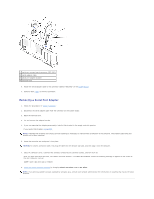
Back to Contents Page Drives Dell™ OptiPlex™ GX280 Systems User's Guide General Installation Guidelines Hard Drive Adding a Second Hard Drive Front-Panel Inserts Floppy Drive CD/DVD Drive Cable Routing Your computer supports: l two serial ATA hard drives l two floppy or optional Zip drives l two CD or DVD drives 1 CD/DVD drive(s) 2 floppy drive(s) 3 hard drive(s) General Installation Guidelines Connect CD/DVD drives to the connector labeled "IDE" on the system board. Serial ATA hard drives should be connected to the connectors labeled "SATA0," SATA1," "SATA2," or "SATA3" on the system board. IDE Drive Addressing When you connect two IDE devices to a single IDE interface cable and configure them for the cable select setting, the device attached to the last connector on the interface cable is the master or boot device (drive 0), and the device attached to the middle connector on the interface cable is the slave device (drive 1). See the drive documentation in your upgrade kit for information on configuring devices for the cable select setting. Connecting Drive Cables When you install a drive, you connect two cables-a DC power cable and a data cable-to the back of the drive and to the system board. Drive Interface Connectors
-
 1
1 -
2
-
3
-
4
-
5
-
6
-
7
-
8
-
9
-
10
-
11
-
12
-
13
-
14
-
15
-
16
-
17
-
18
-
19
-
20
-
21
-
22
-
23
-
24
-
25
-
26
-
27
-
28
-
29
-
30
-
31
-
32
-
33
-
34
-
35
-
36
-
37
-
38
-
39
-
40
-
41
-
42
-
43
-
44
-
45
-
46
-
47
-
48
-
49
-
50
-
51
-
52
-
53
-
54
-
55
-
56
-
57
-
58
-
59
-
60
-
61
-
62
-
63
-
64
-
65
-
66
-
67
-
68
-
69
-
70
-
71
-
72
-
73
-
74
-
75
-
76
-
77
-
78
-
79
-
80
-
81
-
82
-
83
-
84
-
85
-
86
-
87
-
88
-
89
-
90
-
91
-
92
-
93
-
94
-
95
-
96
-
97
-
98
-
99
-
100
-
101
-
102
-
103
-
104
-
105
-
106
-
107
-
108
-
109
-
110
-
111
-
112
-
113
-
114
-
115
-
116
-
117
-
118
-
119
-
120
-
121
-
122
-
123
-
124
-
125
-
126
-
127
-
128
-
129
-
130
-
131
-
132
-
133
-
134
-
135
-
136
-
137
-
138
-
139
-
140
-
141
-
142
-
143
-
144
-
145
-
146
-
147
-
148
-
149
-
150
-
151
-
152
-
153
-
154
-
155
-
156
-
157
-
158
-
159
-
160
-
161
-
162
-
163
-
164
-
165
-
166
-
167
-
168
-
169
-
170
-
171
-
172
-
173
-
174
-
175
-
176
-
177
-
178
-
179
-
180
-
181
-
182
-
183
-
184
-
185
-
186
-
187
-
188
-
189
-
190
-
191
-
192
-
193
-
194
-
195
-
196
-
197
-
198
-
199
-
200
-
201
-
202
-
203
-
204
-
205
-
206
-
207
-
208
-
209
-
210
-
211
-
212
-
213
-
214
-
215
-
216
-
217
-
218
-
219
-
220
-
221
-
222
-
223
-
224
-
225
-
226
-
227
-
228
-
229
-
230
-
231
-
232
-
233
-
234
-
235
-
 236
236 -
 237
237 -
 238
238 -
 239
239 -
 240
240 -
 241
241 -
 242
242 -
 243
243 -
 244
244 -
 245
245 -
 246
246 -
247
-
248
-
249
-
250
-
251
-
252
-
253
-
254
-
255
-
256
-
257
-
258
-
259
-
260
-
261
-
262
-
263
-
264
-
265
-
266
-
267
-
268
-
269
-
270
-
271
-
272
-
273
-
274
-
275
-
276
-
277
-
278
-
279
-
280
-
281
-
282
-
283
-
284
-
285
-
286
-
287
-
288
-
289
 |
 |
