Dell GX280DT User Guide - Page 165
Chassis Intrusion, On-Silent, Audio Controller, Network Controller
 |
UPC - 851846002006
View all Dell GX280DT manuals
Add to My Manuals
Save this manual to your list of manuals |
Page 165 highlights
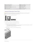
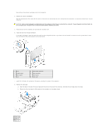
9. Reconnect any cables that you removed in step 2. 10. Connect any cables that should be attached to the card. See the documentation for the card for information about the card's cable connections. NOTICE: Do not route card cables over or behind the cards. Cables routed over the cards can prevent the computer cover from closing properly or cause damage to the equipment. 11. Close the computer cover. 12. Attach the computer stand (optional). NOTICE: To connect a network cable, first plug the cable into the network wall jack and then plug it into the computer. 13. Connect your computer and devices to electrical outlets, and turn them on. After you open and close the cover, the chassis intrusion detector, if installed and enabled, causes the following message to appear on the screen at the next computer start-up: ALERT! Cover was previously removed. 14. Reset the chassis intrusion detector by changing Chassis Intrusion to On or On-Silent. NOTE: If an admin password has been assigned by someone else, contact your network administrator for information on resetting the chassis intrusion detector. 15. If you installed a sound card, perform the following steps: a. Enter system setup, select Audio Controller, and change the setting to Off. b. Connect external audio devices to the sound card's connectors. Do not connect external audio devices to the microphone, speaker/headphone, or line-in connectors on the back panel. 16. If you installed an add-in network adapter and want to turn off the integrated network adapter: a. Enter system setup, select Network Controller and change the setting to Off. b. Connect the network cable to the add-in network adapter's connectors. Do not connect the network cable to the integrated connector on the back panel. 17. Install any drivers required for the card as described in the card documentation. Removing a PCI Card 1. Follow the procedures in "Before You Begin." 2. Remove the card cage (see step 2 of the previous procedure). 3. Press the lever on the retention arm and raise the retention arm. 4. If necessary, disconnect any cables connected to the card. 5. Grasp the card by its top corners, and ease it out of its connector. 6. If you are removing the card permanently, install a filler bracket in the empty card-slot opening. If you need a filler bracket, contact Dell. NOTE: Installing filler brackets over empty card-slot openings is necessary to maintain FCC certification of the computer. The brackets also keep dust and dirt out of your computer. 7. Lower the retention arm and press it into place. NOTICE: To connect a network cable, first plug the cable into the network wall jack and then plug it into the computer. 8. Replace the card cage (see step 8 of the previous procedure). 9. Close the computer cover, reconnect the computer and devices to electrical outlets, and turn them on.
-
 1
1 -
2
-
3
-
4
-
5
-
6
-
7
-
8
-
9
-
10
-
11
-
12
-
13
-
14
-
15
-
16
-
17
-
18
-
19
-
20
-
21
-
22
-
23
-
24
-
25
-
26
-
27
-
28
-
29
-
30
-
31
-
32
-
33
-
34
-
35
-
36
-
37
-
38
-
39
-
40
-
41
-
42
-
43
-
44
-
45
-
46
-
47
-
48
-
49
-
50
-
51
-
52
-
53
-
54
-
55
-
56
-
57
-
58
-
59
-
60
-
61
-
62
-
63
-
64
-
65
-
66
-
67
-
68
-
69
-
70
-
71
-
72
-
73
-
74
-
75
-
76
-
77
-
78
-
79
-
80
-
81
-
82
-
83
-
84
-
85
-
86
-
87
-
88
-
89
-
90
-
91
-
92
-
93
-
94
-
95
-
96
-
97
-
98
-
99
-
100
-
101
-
102
-
103
-
104
-
105
-
106
-
107
-
108
-
109
-
110
-
111
-
112
-
113
-
114
-
115
-
116
-
117
-
118
-
119
-
120
-
121
-
122
-
123
-
124
-
125
-
126
-
127
-
128
-
129
-
130
-
131
-
132
-
133
-
134
-
135
-
136
-
137
-
138
-
139
-
140
-
141
-
142
-
143
-
144
-
145
-
146
-
147
-
148
-
149
-
150
-
151
-
152
-
153
-
154
-
155
-
156
-
157
-
158
-
159
-
 160
160 -
 161
161 -
 162
162 -
 163
163 -
 164
164 -
 165
165 -
 166
166 -
 167
167 -
 168
168 -
 169
169 -
 170
170 -
171
-
172
-
173
-
174
-
175
-
176
-
177
-
178
-
179
-
180
-
181
-
182
-
183
-
184
-
185
-
186
-
187
-
188
-
189
-
190
-
191
-
192
-
193
-
194
-
195
-
196
-
197
-
198
-
199
-
200
-
201
-
202
-
203
-
204
-
205
-
206
-
207
-
208
-
209
-
210
-
211
-
212
-
213
-
214
-
215
-
216
-
217
-
218
-
219
-
220
-
221
-
222
-
223
-
224
-
225
-
226
-
227
-
228
-
229
-
230
-
231
-
232
-
233
-
234
-
235
-
236
-
237
-
238
-
239
-
240
-
241
-
242
-
243
-
244
-
245
-
246
-
247
-
248
-
249
-
250
-
251
-
252
-
253
-
254
-
255
-
256
-
257
-
258
-
259
-
260
-
261
-
262
-
263
-
264
-
265
-
266
-
267
-
268
-
269
-
270
-
271
-
272
-
273
-
274
-
275
-
276
-
277
-
278
-
279
-
280
-
281
-
282
-
283
-
284
-
285
-
286
-
287
-
288
-
289
 |
 |
