Dell GX280DT User Guide - Page 238
serial adapter cable
 |
UPC - 851846002006
View all Dell GX280DT manuals
Add to My Manuals
Save this manual to your list of manuals |
Page 238 highlights
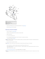
1 serial port system board connector (SER_PS2) 2 serial adapter cable 3 serial port adapter bracket 4 retention arm 6. Attach the serial adapter cable to the connector labeled "SER_PS2" on the system board. 7. Continue with step 7 in the next procedure. Removing a Serial Port Adapter 1. Follow the procedures in "Before You Begin." 2. Disconnect the serial adapter cable from the connector on the system board. 3. Raise the retention arm. 4. Lift and remove the adapter bracket. 5. If you are removing the adapter permanently, install a filler bracket in the empty card-slot opening. If you need a filler bracket, contact Dell. NOTE: Installing filler brackets over empty card-slot openings is necessary to maintain FCC certification of the computer. The brackets also keep dust and dirt out of your computer. 6. Lower the retention arm and press it into place. NOTICE: To connect a network cable, first plug the cable into the network wall jack, and then plug it into the computer. 7. Close the computer cover, reconnect the computer and devices to electrical outlets, and turn them on. After you open and close the cover, the chassis intrusion detector, if installed and enabled, causes the following message to appear on the screen at the next computer start-up: ALERT! Cover was previously removed. 8. Reset the chassis intrusion detector by changing Chassis Intrusion to On or On-Silent. NOTE: If an admin password has been assigned by someone else, contact your network administrator for information on resetting the chassis intrusion detector.
-
 1
1 -
2
-
3
-
4
-
5
-
6
-
7
-
8
-
9
-
10
-
11
-
12
-
13
-
14
-
15
-
16
-
17
-
18
-
19
-
20
-
21
-
22
-
23
-
24
-
25
-
26
-
27
-
28
-
29
-
30
-
31
-
32
-
33
-
34
-
35
-
36
-
37
-
38
-
39
-
40
-
41
-
42
-
43
-
44
-
45
-
46
-
47
-
48
-
49
-
50
-
51
-
52
-
53
-
54
-
55
-
56
-
57
-
58
-
59
-
60
-
61
-
62
-
63
-
64
-
65
-
66
-
67
-
68
-
69
-
70
-
71
-
72
-
73
-
74
-
75
-
76
-
77
-
78
-
79
-
80
-
81
-
82
-
83
-
84
-
85
-
86
-
87
-
88
-
89
-
90
-
91
-
92
-
93
-
94
-
95
-
96
-
97
-
98
-
99
-
100
-
101
-
102
-
103
-
104
-
105
-
106
-
107
-
108
-
109
-
110
-
111
-
112
-
113
-
114
-
115
-
116
-
117
-
118
-
119
-
120
-
121
-
122
-
123
-
124
-
125
-
126
-
127
-
128
-
129
-
130
-
131
-
132
-
133
-
134
-
135
-
136
-
137
-
138
-
139
-
140
-
141
-
142
-
143
-
144
-
145
-
146
-
147
-
148
-
149
-
150
-
151
-
152
-
153
-
154
-
155
-
156
-
157
-
158
-
159
-
160
-
161
-
162
-
163
-
164
-
165
-
166
-
167
-
168
-
169
-
170
-
171
-
172
-
173
-
174
-
175
-
176
-
177
-
178
-
179
-
180
-
181
-
182
-
183
-
184
-
185
-
186
-
187
-
188
-
189
-
190
-
191
-
192
-
193
-
194
-
195
-
196
-
197
-
198
-
199
-
200
-
201
-
202
-
203
-
204
-
205
-
206
-
207
-
208
-
209
-
210
-
211
-
212
-
213
-
214
-
215
-
216
-
217
-
218
-
219
-
220
-
221
-
222
-
223
-
224
-
225
-
226
-
227
-
228
-
229
-
230
-
231
-
232
-
 233
233 -
 234
234 -
 235
235 -
 236
236 -
 237
237 -
 238
238 -
 239
239 -
 240
240 -
 241
241 -
 242
242 -
 243
243 -
244
-
245
-
246
-
247
-
248
-
249
-
250
-
251
-
252
-
253
-
254
-
255
-
256
-
257
-
258
-
259
-
260
-
261
-
262
-
263
-
264
-
265
-
266
-
267
-
268
-
269
-
270
-
271
-
272
-
273
-
274
-
275
-
276
-
277
-
278
-
279
-
280
-
281
-
282
-
283
-
284
-
285
-
286
-
287
-
288
-
289
 |
 |
