Dell Precision T5400 User's Guide
Dell Precision T5400 Manual
 |
View all Dell Precision T5400 manuals
Add to My Manuals
Save this manual to your list of manuals |
Dell Precision T5400 manual content summary:
- Dell Precision T5400 | User's Guide - Page 1
Dell Precision™ T5400 User's Guide Model DCTA www.dell.com | support.dell.com - Dell Precision T5400 | User's Guide - Page 2
of data and tells you how to avoid the problem. CAUTION: A CAUTION indicates a potential for property Dell, the DELL logo, Dell Precision, and Dell OpenManage are trademarks of Dell Inc.; Intel, Speedstep, and Xeon are registered trademarks of Intel Corporation; Microsoft, Windows, and Windows - Dell Precision T5400 | User's Guide - Page 3
26 Inside View - Hard Drive Bay Rotated Out . . . . 27 System Board Components 28 Cable Colors 29 Changing Between Tower and Desktop Modes . . . . 30 Specifications 36 3 Advanced Features 45 LegacySelect Technology Control 45 Manageability 45 Alert Standard Format 45 Dell OpenManage™ IT - Dell Precision T5400 | User's Guide - Page 4
Dell OpenManage Client Instrumentation . . . . . 47 Power Management 47 About RAID Configurations 49 RAID Level 0 50 RAID Level 1 51 RAID Level 5 51 Configuring Your Computer for RAID 53 Configuring Your Computer for RAID Using the Intel Matrix Storage Manager 53 Configuring Your Computer for - Dell Precision T5400 | User's Guide - Page 5
Resetting the Chassis Intrusion Detector . . . . . 76 Security Cable Lock 77 Passwords 78 About Passwords 78 Using a Primary (or System) Password 79 Using an Administrator Password 82 Disabling a Forgotten Password and Setting a New Password 84 Trusted Platform Module (TPM 85 Enabling the TPM - Dell Precision T5400 | User's Guide - Page 6
Monitor 105 Floppy Drive 105 CDs and DVDs 105 9 Troubleshooting 107 Solving Problems 107 Battery Problems 107 Drive Problems 107 E-Mail and Internet Problems 109 Error Messages 110 IEEE 1394 Device Problems 111 Keyboard Problems 112 Lockups and Software Problems 112 Memory Problems 114 - Dell Precision T5400 | User's Guide - Page 7
POST 121 Diagnostic Light Codes During POST 123 Beep Codes 129 Error Messages 130 Dell Diagnostics 136 When to Use the Dell Diagnostics 136 Starting the Dell Diagnostics From Your Hard Drive 137 Starting the Dell Diagnostics From the Drivers and Utilities Disc 137 Dell Diagnostics Main Menu - Dell Precision T5400 | User's Guide - Page 8
Working Inside Your Computer 152 Removing the Computer Cover and Front Panel . . . . 153 Removing the Computer Cover 153 Removing the Front Panel 155 Rotating the Hard Drive Processor 179 Installing the Processor 183 Memory 187 Fully Buffered DIMM (FBD) Memory Overview . . 187 8 Contents - Dell Precision T5400 | User's Guide - Page 9
Memory 189 Installing Memory 190 Cards 193 Expansion Card Support 193 Installing an Expansion Card 194 Removing an Expansion Card 201 Drives 205 Tower Computer Drives 205 Desktop Computer Drives 206 Controller Card Data Cable Connectors 212 Hard Drive 212 Drive Panels 233 Floppy Drive - Dell Precision T5400 | User's Guide - Page 10
Returning Items for Warranty Repair or Credit . . . . . 292 Before You Call 292 Contacting Dell 295 A Appendix 297 FCC Notice (U.S. Only 297 FCC Class B 297 Glossary 299 10 Contents - Dell Precision T5400 | User's Guide - Page 11
1 Finding Information NOTE: Some features or media may be optional and may not ship with your computer. Some features or media may not be available in certain countries. NOTE: Additional information may ship with your computer. Finding Information 11 - Dell Precision T5400 | User's Guide - Page 12
and Utilities disc to reinstall drivers (see "Reinstalling Drivers and Utilities" on page 142), or to run the Dell Diagnostics (see "Dell Diagnostics" on page 136). Readme files may be included on your Drivers and Utilities disc to provide lastminute updates about technical changes to your computer - Dell Precision T5400 | User's Guide - Page 13
• How to run the Dell Diagnostics • How to set up a printer • How to open my computer Find It Here Quick Reference Guide NOTE: This document may be optional and may not ship with your computer. • Warranty information • Terms and Conditions (U.S. only) • Safety instructions • Regulatory information - Dell Precision T5400 | User's Guide - Page 14
and Express Service Code • Microsoft Windows License Label Find It Here Service Tag and Microsoft® Windows® License These labels are located on your computer. • Use the Service Tag to identify your computer when you use support.dell.com or contact support. • Enter the Express Service Code to direct - Dell Precision T5400 | User's Guide - Page 15
Dell customers • Upgrades - Upgrade information for components, such as memory, the hard drive, and the operating system • Customer Care - Contact information, service call and order status, warranty, and repair information • Service and support - Service call status and support history, service - Dell Precision T5400 | User's Guide - Page 16
Windows Help and Support 1 Click the Windows Vista Start button , and then click Help and Support. 2 In Search Help, type a word or phrase that describes your problem, and then press or click the magnifying glass. 3 Click the topic that describes your problem. 4 Follow the instructions - Dell Precision T5400 | User's Guide - Page 17
It Here • How to use Linux Dell Supported Linux Sites • E-mail discussions with users of Dell Precision™ products and the Linux operating system • Additional information regarding Linux and my Dell Precision computer • Linux.dell.com • Lists.us.dell.com/mailman/listinfo/linuxprecision Finding - Dell Precision T5400 | User's Guide - Page 18
18 Finding Information - Dell Precision T5400 | User's Guide - Page 19
bay 2 lower 5.25-inch drive bay 3 FlexBay 4 hard-drive activity light Use this bay for an optical drive. Use this bay for an optional optical drive. Use this bay for an optional third hard drive (SATA or SAS), a floppy drive, or a Media Card Reader. The hard drive light is on when the computer - Dell Precision T5400 | User's Guide - Page 20
you connect occasionally, such as flash memory keys or cameras, or for bootable 7 Dell™ rotatable badge To rotate the Dell badge for tower-to diagnostic lights (4) Use these lights to help you troubleshoot a computer problem based on the diagnostic code. For more information, see "Diagnostic Lights - Dell Precision T5400 | User's Guide - Page 21
) support halflength cards. Plug USB, audio, and other devices into the appropriate connector (see "Back Panel Connectors (Tower Orientation)" on page 22 for more information. CAUTION: Ensure that none of the system air vents are blocked. Blocking them will cause serious thermal problems. About - Dell Precision T5400 | User's Guide - Page 22
automatically disabled if the computer detects an installed card containing a parallel connector configured to the same address. For more information, integrated amplifiers. On computers with a sound card, use the connector on the card. 5 link integrity light Green - A good connection exists between - Dell Precision T5400 | User's Guide - Page 23
an additional network connector card, use the connectors on the card and on the back ensure reliable operation. 7 network activity light Flashes a yellow light when the computer is transmitting or that you connect occasionally, such as flash memory keys or cameras, or for bootable USB devices - Dell Precision T5400 | User's Guide - Page 24
45 6 7 12 11 10 9 8 1 upper 5.25-inch drive bay Use this bay for an an optical drive. 2 lower 5.25-inch drive bay Use this bay for an optional optical drive or a SATA hard drive. 3 FlexBay Use this bay for a floppy drive or a Media Card Reader. 4 IEEE 1394 connector (optional) Use the - Dell Precision T5400 | User's Guide - Page 25
Mbps, or 1000-Mbps (or 1-Gbps) network and the computer. 12 diagnostic lights (4) Use these lights to help you troubleshoot a computer problem based on the diagnostic code. For more information, see "Diagnostic Lights" on page 121. Back View (Desktop Orientation) 1 2 3 About Your Computer 25 - Dell Precision T5400 | User's Guide - Page 26
, USB, and other devices into the appropriate connector. 2 card slots Access connectors for any installed PCI and PCI Express cards. Slots 2-4 support full-length cards: • two PCI Express x16 slots • one PCI slot Slots 1, 5, and 6 support half-length cards: • two PCI-X slots • one PCI Express x8 - Dell Precision T5400 | User's Guide - Page 27
1 power supply 3 FlexBay 5 upper 5.25-inch drive bay 2 rotatable hard drive bay 4 lower 5.25-inch drive bay Inside View - Hard Drive Bay Rotated Out 1 2 3 5 4 1 power supply 4 front fan 2 system board 5 card fan 3 memory fan About Your Computer 27 - Dell Precision T5400 | User's Guide - Page 28
System Board Components 1 23 45 6 7 8 9 10 11 12 13 14 28 15 16 27 17 18 19 26 25 24 23 22 21 20 28 About Your Computer - Dell Precision T5400 | User's Guide - Page 29
) 24 front panel audio connector (FP_AUDIO) 25 PCI Express x8 card slot, wired as x4 26 hard drive fan connector (FAN_HDD) (SLOT1_PCIE) 27 memory module connectors (DIMM_1-8) 28 memory fan connector (FAN_MEM) Cable Colors Device SATA hard drive floppy drive optical drive front panel Color - Dell Precision T5400 | User's Guide - Page 30
of an optional kit from Dell, you can change the configuration of your Dell Precision computer between desktop and tower modes. NOTE: The tower configuration supports a third SAS or SATA hard drive in the FlexBay. The desktop configuration only supports a third SATA drive. 30 About Your Computer - Dell Precision T5400 | User's Guide - Page 31
page 151. 2 Remove the computer cover (see "Removing the Computer Cover" on page 153). 3 If converting from a tower configuration to a desktop configuration, find the spare card retainer beside the card fan, pull its retention tab out from the surrounding metal and pull it up, away from the chassis - Dell Precision T5400 | User's Guide - Page 32
1 2 1 spare card retainer 2 card fan 4 Remove the drive panel (see "Removing the Drive Panel" on page 233). 5 Prepare the computer's new drive panel by adding or removing inserts as needed (see "Drive Panels" on page 233). If spare screws are attached to the old drive panel, you may transfer - Dell Precision T5400 | User's Guide - Page 33
in your computer and you are converting from desktop to tower mode (see "About the Metal Shields Present in Some Drive Configurations" on page 207), remove the vented metal insert from the FlexBay if the bay is empty or has an optional third hard drive installed in it: a Pull the vented metal insert - Dell Precision T5400 | User's Guide - Page 34
page 193). 10 Rotate the Dell badge by turning the plastic handle on the back of the front panel until the badge is in the correct orientation. 11 Reinstall any optical drives in the new orientation (see "Optical Drive" on page 268). 12 If you had a floppy drive or Media Card Reader installed in the - Dell Precision T5400 | User's Guide - Page 35
the FlexBay and you are changing from a tower to a desktop configuration, remove its four screws and install the hard drive into the drive carrier (see "Hard Drive" on page 212). NOTE: Hard-drive screws or a hard-drive carrier can be ordered from Dell. See "Contacting Dell" on page 295. 14 If metal - Dell Precision T5400 | User's Guide - Page 36
page 153). 18 Verify that your computer works correctly by running the "Dell Diagnostics" on page 136. Specifications NOTE: Offerings may vary by region. For more information regarding the configuration of your computer, click Start→ Help and Support and select the option to view information about - Dell Precision T5400 | User's Guide - Page 37
type Internal cache External bus frequency Memory Memory module connectors Memory module capacities Memory type Minimum memory Maximum memory BIOS address System Information System chipset Data bus width DRAM bus width Processor address bus width Flash EPROM Graphics bus Dual-Core Intel® Xeon - Dell Precision T5400 | User's Guide - Page 38
two PCI-X slots • one PCI Express x8 slot Tower Mode: Slots 2-5 support full-length cards: • one PCI-X slot • two PCI Express x16 slots • one PCI slot Slots 1 and 6 support half-length cards: • one PCI-X slot • one PCI Express x8 slot Cards supported PCI 2.3 PCI Express 1.0A in slot 1 PCI - Dell Precision T5400 | User's Guide - Page 39
Network adapter PS/2 (keyboard and mouse) USB Audio System board connectors Floppy drive two 9-pin connectors; 16550C-compatible 25-hole connector (bidirectional) one front-panel 6-pin connector and one rear panel 6-pin connector RJ45 connector two 6-pin mini-DIN two front-panel and five back-panel - Dell Precision T5400 | User's Guide - Page 40
) two 5.25-inch drive bays two 3.5-inch hard-drive bays starts embedded system setup (during startup only) starts the Boot Device menu (during start-up only) launches the utility partition (if installed) during start-up runs onboard diagnostics Controls and Lights Power control push button 40 - Dell Precision T5400 | User's Guide - Page 41
Controls and Lights Power light Hard-drive access light Network integrity lights Activity light Diagnostic lights Standby power light Power DC power supply Wattage Heat dissipation Voltage Backup battery Front panel: green light-blinking green in sleep state; solid green for power-on state amber - Dell Precision T5400 | User's Guide - Page 42
Width Depth Weight Supported monitor weight (in desktop orientation) Environmental Temperature range Operating Storage Relative humidity (maximum) Operating Storage Maximum vibration (using a random-vibration spectrum that simulates user environment) Operating Storage Maximum shock Operating Storage - Dell Precision T5400 | User's Guide - Page 43
About Your Computer 43 - Dell Precision T5400 | User's Guide - Page 44
44 About Your Computer - Dell Precision T5400 | User's Guide - Page 45
-reduced, or legacyfree solutions based on common platforms, hard-drive images, and help desk procedures. Control is provided to the administrator through system setup, Dell OpenManage™ IT Assistant, or Dell custom factory integration. LegacySelect allows administrators to electronically activate - Dell Precision T5400 | User's Guide - Page 46
Critical Fan Failure The fan speed (rpm) is out of limits. Connectivity: Ethernet Connectivity Enabled/ Ethernet Connectivity Disabled The Ethernet connectivity is enabled or the Ethernet connectivity is disabled. For more information about Dell's ASF implementation, see the ASF User's Guide and - Dell Precision T5400 | User's Guide - Page 47
. For information about Dell OpenManage Client Instrumentation, see the Dell OpenManage Client Instrumentation User's Guide available on the Dell Support website at support.dell.com. Power Management Your computer can be set to use less power when you are not working. You control the power usage - Dell Precision T5400 | User's Guide - Page 48
memory remains active. NOTE: Hibernate mode is only supported on computers with 4-GB of RAM or less. • Hibernate. This sleep mode reduces power consumption to a minimum by writing all data in system memory to a hard drive Standby Hibernate Shutdown Wake-Up Methods (Windows XP) • Press the power - Dell Precision T5400 | User's Guide - Page 49
better or worse than a RAID level 0 configuration. The Intel RAID controller on your computer can only create a RAID level 0 configuration using two or three physical drives. If a third drive is present, then that drive can be made part of a RAID level 0 configuration using the Advanced Features - Dell Precision T5400 | User's Guide - Page 50
and two are in a RAID level 1 configuration, the third drive can be used as a spare drive for the RAID configuration (see "Creating a Spare Hard Drive" on page 60). A RAID level 5 array must be made up of three drives. All drives must be the same type of drive; SAS and SATA drives cannot be mixed in - Dell Precision T5400 | User's Guide - Page 51
. serial ATA RAID configured for RAID level 1 segment 1 segment 2 segment 3 segment 4 segment 5 segment 6 hard drive 1 segment 1 drive. Also, because data is duplicated on both drives, two 120-GB RAID level 1 drives collectively have a maximum of 120-GB on which to store data. RAID Level 5 RAID - Dell Precision T5400 | User's Guide - Page 52
block 1 half of data block 2 half of data block 3 half of data block 4 parity data for block 5 half of data block 6 hard drive 3 Because data is striped across the RAID configuration, as it is in a RAID 0 configuration, it can be quickly accessed. Also, because of the parity data, if only a single - Dell Precision T5400 | User's Guide - Page 53
your computer. You must have at least two hard drives installed in your computer to set up a RAID configuration. For instructions on how to install a hard drive, see "Cards" on page 193. To configure a RAID hard drive volume, use the Intel RAID Option ROM utility before you install the operating - Dell Precision T5400 | User's Guide - Page 54
and you want to configure the two new drives into a RAID volume. • You already have a two-hard drive computer configured into a volume, but you still have some space left on the volume that you want to designate as a second RAID volume. Creating a RAID Level 0 Configuration NOTICE: When you perform - Dell Precision T5400 | User's Guide - Page 55
click Next to continue. 6 On the Select Volume Location screen, click the first hard drive you want to use to create your RAID level 1 volume, and then click the right arrow. Click a second hard drive until two drives appear in the Selected window, and then click Next. 7 In the Specify Volume Size - Dell Precision T5400 | User's Guide - Page 56
Back to make changes. 10 Follow Microsoft Windows procedures for creating a partition on the new RAID volume. Deleting a RAID Volume NOTICE: While this procedure deletes the RAID 1 volume, it also splits the RAID 1 volume into two non-RAID hard drives with a partition, and leaves any existing data - Dell Precision T5400 | User's Guide - Page 57
not see an Actions menu option, you have not yet set your computer to RAID-enabled mode (see "Setting Your Computer to RAIDEnabled Mode" on page 53). 3 On the Actions menu, select Create RAID Volume From Existing Hard Drive to launch the Migration Wizard. 4 Click Next on the Migration Wizard screen - Dell Precision T5400 | User's Guide - Page 58
. Migrating to a RAID Level 1 Configuration 1 Set your computer to RAID-enabled mode (see "Setting Your Computer to RAID-Enabled Mode" on page RAID-enabled mode (see "Setting Your Computer to RAIDEnabled Mode" on page 53). 3 On the Actions menu, click Create RAID Volume From Existing Hard Drive - Dell Precision T5400 | User's Guide - Page 59
Select Member Hard Drive screen, double-click the hard drive to select the member drive that you want to act as the mirror in the configuration, and RAID-enabled mode (see "Setting Your Computer to RAIDEnabled Mode" on page 53). 3 On the Actions menu, click Create RAID Volume From Existing Hard Drive - Dell Precision T5400 | User's Guide - Page 60
of the two drives in the RAID configuration that it supports. Otherwise, the spare hard drive will not function. The RAID utility will not notify you if you fail to select a large enough drive. A spare hard drive may be created with a RAID level 1 configuration. The spare hard drive will not be - Dell Precision T5400 | User's Guide - Page 61
. Do not use the following procedure to migrate an existing storage configuration to RAID level 0 configuration. Creating a RAID Level 0 Configuration NOTICE: You will lose any data on your hard drives when you create a RAID configuration using the following procedure. Back up data that you want to - Dell Precision T5400 | User's Guide - Page 62
and press . 13 Install the operating system (see "Reinstalling Windows XP or Windows Vista" on page 149.) Creating a RAID Level 1 Configuration NOTICE: You will lose any data on your hard drives when you create a RAID configuration using the following procedure. Back up data that you want to - Dell Precision T5400 | User's Guide - Page 63
and press . 12 Install the operating system (see "Reinstalling Windows XP or Windows Vista" on page 149.) Creating a RAID Level 5 Configuration NOTICE: You will lose any data on your hard drives when you create a RAID configuration using the following procedure. Back up data that you want to - Dell Precision T5400 | User's Guide - Page 64
Volume NOTICE: When you perform this operation, all data on the RAID drives will be lost. NOTICE: If your computer currently boots to RAID and you delete the RAID volume in the Intel RAID Option ROM utility, your computer will become unbootable. 1 Press when you are prompted to enter the - Dell Precision T5400 | User's Guide - Page 65
the guidelines below when installing your computer in an enclosure: NOTICE: The operating temperature specifications indicated in this manual reflects the maximum ambient operating temperature. The room ambient temperature needs to be a consideration when installing your computer in an enclosure - Dell Precision T5400 | User's Guide - Page 66
• If your computer is installed in a corner on a desk or under a desk, leave at least 5.1 cm (2 in) clearance from the back of the computer to the wall to permit the airflow required for proper ventilation. 66 Setting Up Your Computer - Dell Precision T5400 | User's Guide - Page 67
and ISP offerings vary by country. For further information on troubleshooting e-mail and internet problems, see "E-Mail and Internet Problems" on page 109. To connect to the Internet, you need a modem or network connection and an Internet service provider (ISP). Your ISP will offer one or more of - Dell Precision T5400 | User's Guide - Page 68
. 2 Double-click the ISP icon on the Microsoft® Windows® desktop. 3 Follow the instructions on the screen to complete the setup. If you do service providers (ISPs). • If you have already obtained setup information from your ISP but you did not receive a setup disc, click Set up my connection manually - Dell Precision T5400 | User's Guide - Page 69
Next. If you selected Set up my connection manually, continue to step 6. Otherwise, follow the instructions on the screen to complete the setup. NOTE: Windows Vista Start button , and click Control Panel 3 Under Network and Internet, click Connect to the Internet. The Connect to the Internet window - Dell Precision T5400 | User's Guide - Page 70
, you must access the Network Connections utility from the Control Panel and perform additional configuration steps, such as setting up an advanced connection and designating the host computer and the guest computer. For instructions on setting up a direct cable connection between two computers - Dell Precision T5400 | User's Guide - Page 71
. Do not click Next at this time. To copy data from the old computer: 1 On the old computer, insert the Windows XP Operating System disc. 2 On the Welcome to Microsoft Windows XP screen, click Perform additional tasks. 3 Under What do you want to do?, click Transfer files and settings→ Next. 4 On - Dell Precision T5400 | User's Guide - Page 72
, click Next. 3 On the Which computer is this? screen, click New Computer→ Next. 4 On the Do you have a Windows XP CD? screen, click I want to create a Wizard Disk in the following drive→ Next. 5 Insert the removable media, such as a writable CD, and click OK. 6 When the disk creation completes and - Dell Precision T5400 | User's Guide - Page 73
then click Transfer files and settings→ Start Windows Easy Transfer. 2 In the User Account Control dialog box, click Continue. 3 Click Start a new transfer or Continue a transfer in progress. Follow the instructions provided on the screen by the Windows Easy Transfer wizard. Power Protection Devices - Dell Precision T5400 | User's Guide - Page 74
. See the surge protector documentation for modem connection instructions. NOTICE: Not all surge protectors offer network adapter power while data is being saved to the hard drive may result in data loss or file damage. NOTE: To ensure maximum battery operating time, connect only your computer - Dell Precision T5400 | User's Guide - Page 75
Your Computer Chassis Intrusion Detection CAUTION: Before you begin any of the procedures in this section, follow the safety instructions in the Product Information Guide. CAUTION: To guard against electrical shock, always unplug your computer from the electrical outlet before opening the cover - Dell Precision T5400 | User's Guide - Page 76
your computer and devices to electrical outlets, and turn them on. Resetting the Chassis Intrusion Detector 1 Turn on (or restart) your computer. 2 When the blue DELL™ logo appears, press immediately. 76 Securing Your Computer - Dell Precision T5400 | User's Guide - Page 77
operating system logo appears, continue to wait until you see the Microsoft® Windows® desktop. Then shut down your computer (see "Turning Off Your . NOTE: Before you purchase an antitheft device, make sure that it works with the security cable slot on your computer. Antitheft devices usually include - Dell Precision T5400 | User's Guide - Page 78
About Passwords NOTE: Passwords are disabled when you receive your computer. A primary (or system) password, an administrator password, and a hard drive password all prevent unauthorized access to your computer in different ways. The following table identifies types and features of passwords - Dell Precision T5400 | User's Guide - Page 79
not support hard drive passwords. NOTICE: Passwords provide a high level of security for data in your computer or hard drive. However, they are not foolproof. If you require more security, obtain and use additional forms of protection, such as smart cards, data encryption programs, or PC Cards with - Dell Precision T5400 | User's Guide - Page 80
left-arrow key. The password is not case sensitive. Certain key combinations are not valid. If you enter one of these combinations, the speaker emits a beep. As you press each character key (or the spacebar for a blank space), a placeholder appears in the field. 5 Press . If the new system - Dell Precision T5400 | User's Guide - Page 81
6 To confirm your password, type it a second time in the Confirm New Password field and press . 7 Press at the prompt. The system password setting changes to Set. 8 Exit the system setup program. Password protection takes effect when you restart the computer. Typing Your System - Dell Precision T5400 | User's Guide - Page 82
field, and then press . 4 Type your password into the Old Password field. 5 If you are changing an existing password, follow the instructions in "Assigning a System Password" on page 80, starting from step 4. 6 If you are deleting a password, press in New Password field, leaving - Dell Precision T5400 | User's Guide - Page 83
-arrow key. The password is not case sensitive. Certain key combinations are not valid. If you enter one of these combinations, the speaker emits a beep. As you press each character key (or the spacebar for a blank space), a placeholder appears in the field. 5 Press . If the new administrator - Dell Precision T5400 | User's Guide - Page 84
field, and then press . 3 Type your password into the Old Password field. 4 If you are changing an existing password, follow the instructions in "Assigning an Administrator Password" on page 83, starting from step 4. 5 If you are deleting a password, press in New Password field - Dell Precision T5400 | User's Guide - Page 85
your TPM data and encryption keys, follow the backup procedures documented in the Broadcom Secure Foundation Getting Started Guide. In the event of these backups being incomplete, lost, or damaged, Dell will be unable to assist in the recovery of encrypted data. Enabling the TPM Feature 1 Enable the - Dell Precision T5400 | User's Guide - Page 86
a fingerprint reader, smart card, or password) • Encryption Guide. Computer Tracking Software Computer tracking software may enable you to locate your computer if it is lost or stolen. The software is optional and may be purchased when you order your Dell™ computer, or you can contact your Dell sales - Dell Precision T5400 | User's Guide - Page 87
agency where you live. • If the computer belongs to a company, notify the security office of the company. • Contact Dell customer service to report the missing computer. Provide the computer Service Tag, the case number, and the name, address, and phone number of the law enforcement agency to which - Dell Precision T5400 | User's Guide - Page 88
88 Securing Your Computer - Dell Precision T5400 | User's Guide - Page 89
as follows: • To change the system configuration information after you add, change, or remove any hardware in your computer • To set or change a user-selectable option such as the user password • To read the current amount of memory or set the type of hard drive installed Before you use System Setup - Dell Precision T5400 | User's Guide - Page 90
System System Info Processor Info Memory Info PCI Info Date/Time Boot Sequence (Diskette drive default) Displays the Computer name, BIOS Version number, BIOS Date, Service Tag, Express Service Code, and Asset Tag. Displays the following information for the processor installed in the system: • - Dell Precision T5400 | User's Guide - Page 91
support will recognize USB floppy drives regardless of this setting. Enables (On) or disables (Off) a SATA drive. Displays the Controller type (SATA), Port number the drive is using, Drive ID number, and Capacity. NOTE: SATA 4 can be enabled or disabled when SATA Operation is set to RAID Autodetect - Dell Precision T5400 | User's Guide - Page 92
select Auto to use the add-in Audio controller. Enables or disables the internal USB controller. No Boot enables the controller but disables the ability to boot from a USB device. NOTE: Operating systems with USB support will recognize USB floppy drives regardless of the No Boot setting. Enables - Dell Precision T5400 | User's Guide - Page 93
controller is primary, PCI or PEG. PEG is the appropriate setting for a PCI Express graphics card or cards max value the processor standard CPUID function will support. Some operating systems won't complete installation when the max CPUID function supported is greater than 3. Optimizes the hard drive - Dell Precision T5400 | User's Guide - Page 94
Optimization Fetches an extra line of data into L2 from external memory. Allows users to turn on/off optimization for highbandwidth, verified. Displays the current status of the hard drive's password security feature and allows a new hard drive password to be assigned and verified. Determines the - Dell Precision T5400 | User's Guide - Page 95
Disable memory protection technology. Activates or disables the BIOS module interface of the optional Computrace service from at the time set in Auto Power Time. NOTE: This feature does not work if you turn off your computer using a power strip or surge protector. Auto controller. System Setup 95 - Dell Precision T5400 | User's Guide - Page 96
(On default) Load Defaults Event Log Displays the service tag for your computer. Controls ASF management. • On = Full ASF 2.0 functionality (RMCP) • Alert Only - send ASF messages on event or error • Off - all ASF functionality disabled Some graphics cards require that the SERR message be disabled - Dell Precision T5400 | User's Guide - Page 97
maximum amount of system memory available to the operating system. When set to Off, all system memory is available to the operating system. When set to On, the maximum amount of memory Report (enabled) and an error is detected during POST, the BIOS will display the error message and prompt you to - Dell Precision T5400 | User's Guide - Page 98
• Onboard or USB Floppy Drive - The computer attempts to boot from the floppy drive. If the floppy disk in the drive is not bootable, if no floppy disk is in the drive, or if there is no floppy drive installed in the computer, the computer generates an error message. • Hard Drive (listed by serial - Dell Precision T5400 | User's Guide - Page 99
1 Insert the memory key into a USB port and restart the computer. 2 When F12 = Boot Menu appears in the upper-right corner of the screen, press . The BIOS detects the device and adds the USB device option to the boot menu. 3 See "Selecting the Boot Device for the Current Boot" on page - Dell Precision T5400 | User's Guide - Page 100
Floppy Drive 1 In system setup, set the Diskette Drive option to USB. 2 Save your changes and exit system setup. 3 Connect the USB floppy drive, insert bootable media, and re-boot the system. 4 See "Selecting the Boot Device for the Current Boot" on page 98. 100 System Setup - Dell Precision T5400 | User's Guide - Page 101
7 Clearing Forgotten Passwords CAUTION: Before you begin any of the procedures in this section, follow the safety instructions in the Product Information Guide. NOTICE: This process erases both the system and the administrator passwords. 1 Follow the procedures in "Before You Begin" on page 151. - Dell Precision T5400 | User's Guide - Page 102
see "Replacing the Computer Cover" on page 161). 5 Connect your computer and monitor to electrical outlets, and turn them on. 6 After the Microsoft® Windows® desktop appears on your computer, shut down your computer (see "Turning Off Your Computer" on page 151). 7 Turn off the monitor and disconnect - Dell Precision T5400 | User's Guide - Page 103
procedures in this section, follow the safety instructions in the Product Information Guide. 1 Follow the procedures in "Before BIOS update file for your computer at the Dell Support website at support.dell.com. 3 Click Download Now to download the file. 4 If the Export Compliance Disclaimer window - Dell Precision T5400 | User's Guide - Page 104
downloads to your desktop. 7 Click Close when the Download Complete window appears. The file icon appears on your desktop and is titled the same as the downloaded BIOS update file. 8 Double-click the file icon on the desktop and follow the on-screen instructions. 104 Clearing Forgotten Passwords - Dell Precision T5400 | User's Guide - Page 105
floppy disks to remove contaminants that accumulate during normal operation. CDs and DVDs NOTICE: Always use compressed air to clean the lens in the optical drive, and follow the instructions that come with the compressed-air product. Never touch the lens in the drive. If you notice problems - Dell Precision T5400 | User's Guide - Page 106
2 With a soft, lint-free cloth, gently wipe the bottom of the disk (the unlabeled side) in a straight line from the center to the outer edge of the disk. For stubborn dirt, try using water or a diluted solution of water and mild soap. You can also purchase commercial products that clean disks and - Dell Precision T5400 | User's Guide - Page 107
does not work properly, contact Dell (see "Contacting Dell" on page 295). Drive Problems CAUTION: Before you begin any of the procedures in this section, follow the safety instructions in the Product Information Guide. ENSURE THAT MICROSOFT® WINDOWS® RECOGNIZES THE DRIVE - Troubleshooting 107 - Dell Precision T5400 | User's Guide - Page 108
and Hardware Problems in the Microsoft® Windows® XP and Microsoft Windows Vista™ Operating Systems" on page 143. R U N T H E D E L L D I A G N O S T I C S - See "Dell Diagnostics" on page 136. Optical drive problems NOTE: High-speed optical drive vibration is normal and may cause noise, which does - Dell Precision T5400 | User's Guide - Page 109
Tools→ Check Now. The User Account Control window may appear. If you are an administrator on the computer, click Continue; otherwise, contact your administrator to continue the desired action. 4 Follow the instructions on the screen. E-Mail and Internet Problems CAUTION: Before you begin any of the - Dell Precision T5400 | User's Guide - Page 110
Click Start → All Programs→ Modem Diagnostic Tool. 2 Follow the instructions on the screen to identify and resolve modem problems. Modem diagnostics are not available on all computers. VERIFY THAT THE MODEM IS COMMUNICATING WITH WINDOWS - Windows XP: 1 Click Start→ Control Panel→ Printers and Other - Dell Precision T5400 | User's Guide - Page 111
YS T E M N O T F O U N D - Contact Dell (see "Contacting Dell" on page 295). IEEE 1394 Device Problems CAUTION: Before you begin any of the procedures in this section, follow the safety instructions in the Product Information Guide. NOTE: Your computer supports only IEEE 1394a standard. ENSURE THAT - Dell Precision T5400 | User's Guide - Page 112
"Troubleshooting Software and Hardware Problems in the Microsoft® Windows® XP and Microsoft Windows Vista™ Operating Systems" on page 143. Lockups and Software Problems CAUTION: Before you begin any of the procedures in this section, follow the safety instructions in the Product Information Guide - Dell Precision T5400 | User's Guide - Page 113
H T S - See "Diagnostic Lights" on page 121. ENSURE Compatibility Wizard→ Next. 2 Follow the instructions on the screen. Windows Vista: The Program Compatibility Wizard configures a program so that it runs in an environment similar to non-Windows Vista operating system environments. Troubleshooting - Dell Precision T5400 | User's Guide - Page 114
TO CHECK THE HARD DRIVE, FLOPPY DISKS, CDS, OR DVDS SAVE AND CLOSE ANY OPEN FILES OR PROGRAMS AND SHUT DOWN YOUR COMPUTER THROUGH THE START MENU Memory Problems CAUTION: Before you begin any of the procedures in this section, follow the safety instructions in the Product Information Guide. IF YOU - Dell Precision T5400 | User's Guide - Page 115
the type of memory supported by your computer, see "Memory" on page 187. • Run the Dell Diagnostics (see "Dell Diagnostics" on page 136). Mouse Problems CAUTION: Before you begin any of the procedures in this section, follow the safety instructions in the Product Information Guide. CHECK THE MOUSE - Dell Precision T5400 | User's Guide - Page 116
O O T E R - See "Troubleshooting Software and Hardware Problems in the Microsoft® Windows® XP and Microsoft Windows Vista™ Operating Systems" on page 143. Network Problems CAUTION: Before you begin any of the procedures in this section, follow the safety instructions in the Product Information Guide - Dell Precision T5400 | User's Guide - Page 117
that the electrical outlet is working by testing it with another on page 28). • Remove and then reinstall all memory modules (see "Memory" on page 187). E L I M I N Problems CAUTION: Before you begin any of the procedures in this section, follow the safety instructions in the Product Information Guide - Dell Precision T5400 | User's Guide - Page 118
the Print to the following port(s): setting is USB. Windows Vista: 1 Click Start → Control Panel→ Hardware and Sound→ Printer. 2 If the printer driver. Scanner Problems CAUTION: Before you begin any of the procedures in this section, follow the safety instructions in the Product Information Guide - Dell Precision T5400 | User's Guide - Page 119
off nearby fans, fluorescent lights, or halogen lamps to check for interference. R E I N S T A L L T H E S O U N D D R I V E R - See "Drivers" on page 141. R U N T H E H A R D W A R E TR O U B L E S H O O T E R - See "Troubleshooting Software and Hardware Problems in the Microsoft® Windows® XP and - Dell Precision T5400 | User's Guide - Page 120
120 Troubleshooting - Dell Precision T5400 | User's Guide - Page 121
you begin any of the procedures in this section, follow the safety instructions in the Product Information Guide. To help you troubleshoot a problem, your computer has four lights labeled "1," "2," "3," and "4" on the front. The lights can be "off" or green. When the computer starts normally, the - Dell Precision T5400 | User's Guide - Page 122
(see "Contacting Dell" on page 295). A possible power Perform the procedure in supply or power cable "Power Problems" on failure has occurred. page 116. If the problem is still not resolved, contact Dell for technical assistance (see "Contacting Dell" on page 295). 122 Troubleshooting Tools - Dell Precision T5400 | User's Guide - Page 123
"Contacting Dell" on page 295). A processor mismatch See "Troubleshooting" on exists. page 107 and then to "Processor" on page 179. (blinking) amber Power supply cables are not properly connected. Verify that both power supply cables are plugged in to the motherboard. Diagnostic Light Codes - Dell Precision T5400 | User's Guide - Page 124
card. If the computer starts normally, troubleshoot the last card removed from the computer for resource conflicts (see "Troubleshooting Software and Hardware Problems in the Microsoft® Windows® XP and Microsoft Windows Vista™ Operating Systems" on page 143). 4 If the problem persists, contact Dell - Dell Precision T5400 | User's Guide - Page 125
occurred. A possible floppy or hard drive failure has occurred. Suggested Resolution 1 If the computer has a graphics card, remove the card, reinstall it, and then restart the computer (see "Cards" on page 193). 2 If the problem still exists, install a graphics card that you know works and restart - Dell Precision T5400 | User's Guide - Page 126
not paired, the system will operate with reduced performance and reduced error-correction capability. 5 Press to boot to the operating system. 6 Run the Dell Diagnostics (see "Dell Diagnostics" on page 136). 7 If the memory module passes, shut down the computer (see "Turning Off Your Computer - Dell Precision T5400 | User's Guide - Page 127
the memory modules that you are installing are compatible with your computer (see "Memory" on page 187). • Reinstall the memory modules and restart the computer. • If the problem persists, contact Dell (see "Contacting Dell" on page 295). Watch your monitor for onscreen messages. Troubleshooting - Dell Precision T5400 | User's Guide - Page 128
normally, troubleshoot the last card removed from the computer for resource conflicts (see "Troubleshooting Software and Hardware Problems in the Microsoft® Windows® XP and Microsoft Windows Vista™ Operating Systems" on page 143). 4 If the problem persists, contact Dell (see "Contacting Dell" on - Dell Precision T5400 | User's Guide - Page 129
beep code (code 1-3-1) consists of one beep, a burst of three beeps, and then one beep. This beep code tells you that the computer encountered a memory problem. If your computer beeps during start-up: 1 Write down the beep code on the "Diagnostics Checklist" on page 294. 2 Run the Dell Diagnostics - Dell Precision T5400 | User's Guide - Page 130
code to shadowed memory Math-coprocessor test failure Cache test failure Error Messages Fill out the "Diagnostics Checklist" on page 294 as you complete these checks. CAUTION: Before you begin any of the procedures in this section, follow the safety instructions in the Product Information Guide - Dell Precision T5400 | User's Guide - Page 131
instructions. ALERT! CPU FAN NOT DETECTED - Ensure that the cooling fan and airflow shroud are properly installed and working. ALERT! PREVIOUS ATTEMPTS AT BOOTING THIS SYSTEM HAVE FAILED AT CHECKPOINT [nnnn]. FOR HELP IN RESOLVING THIS PROBLEM, PLEASE NOTE THIS CHECKPOINT AND CONTACT DELL - Dell Precision T5400 | User's Guide - Page 132
"Dell Diagnostics" on page 136). DISKETTE WRITE PROTECTED - Slide the write-protect notch to the open position. DRIVE NOT READY - Put a floppy disk in the drive. GATE A20 FAILURE - See "Lockups and Software Problems" on page 112. HARD-DISK CONFIGURATION ERROR - HARD-DISK CONTROLLER FAILURE - HARD - Dell Precision T5400 | User's Guide - Page 133
FAILURE AT address, READ value EXPECTING value - MEMORY SIZE IN CMOS INVALID - See "Memory Problems" on page 114. NO BOOT DEVICE AVAILABLE - • If the floppy drive is your boot device, ensure that a bootable floppy disk is in the drive. • If the hard drive is your boot device, ensure that the cables - Dell Precision T5400 | User's Guide - Page 134
(see "Dell Diagnostics" on page 136). NON-SYSTEM DISK OR DISK ERROR - Replace the floppy disk with one that has a bootable operating system or remove the floppy disk from drive A and restart the computer. NOT A BOOT DISKETTE - Insert bootable media and restart your computer. NOT ENOUGH MEMORY OR - Dell Precision T5400 | User's Guide - Page 135
or hard drive. See Windows Help for instructions. • If a large number of sectors are defective, back up the data (if possible), and then reformat the floppy disk or hard drive. SEEK ERROR - See "Drive Problems" on page 107. SHUTDOWN FAILURE - Run the Dell Diagnostics. See (see "Dell Diagnostics" on - Dell Precision T5400 | User's Guide - Page 136
floppy drive cannot read the disk. Insert a floppy disk into the drive and try again. Dell Diagnostics CAUTION: Before you begin any of the procedures in this section, follow the safety instructions in the Product Information Guide. When to Use the Dell Diagnostics If you experience a problem with - Dell Precision T5400 | User's Guide - Page 137
the Dell Diagnostics from either your hard drive or from the Drivers and Utilities disc. Starting the Dell Diagnostics From Your Hard Drive 1 Turn on (or restart) your computer. 2 When the DELL™ logo appears, press immediately. NOTE: If you see a message stating that no diagnostics utility - Dell Precision T5400 | User's Guide - Page 138
the error code and problem description and follow the instructions on the screen. If you cannot resolve the error condition, contact Dell (see "Contacting Dell" on page 295). NOTE: The Service Tag for your computer is located at the top of each test screen. If you contact Dell, technical support - Dell Precision T5400 | User's Guide - Page 139
conditions encountered, error codes, and the problem description. Describes the test and may indicate requirements for running the test. Displays your hardware configuration for the selected device. The Dell Diagnostics obtains configuration information for all devices from system setup, memory, and - Dell Precision T5400 | User's Guide - Page 140
140 Troubleshooting Tools - Dell Precision T5400 | User's Guide - Page 141
your operating system. • Connect or install a new device. Identifying Drivers If you experience a problem with any device, identify whether the driver is the source of your problem and, if necessary, update the driver. Microsoft® Windows® XP 1 Click Start→ Control Panel. Reinstalling Software 141 - Dell Precision T5400 | User's Guide - Page 142
at support.dell.com and your Drivers and Utilities disc provide approved drivers for Dell™ computers. If you install drivers obtained from other sources, your computer might not work correctly. Using Windows Device Driver Rollback If a problem occurs on your computer after you install or update - Dell Precision T5400 | User's Guide - Page 143
incorrectly configured, you can use the Hardware Troubleshooter to resolve the incompatibility. To start the Hardware Troubleshooter: Windows XP: 1 Click Start→ Help and Support. 2 Type hardware troubleshooter in the search field and press to start the search. 3 In the Fix a Problem section - Dell Precision T5400 | User's Guide - Page 144
• Dell PC Restore by Symantec (available in Windows XP) and Dell Factory Image Restore (available in Windows Vista) returns your hard drive to the the hard drive. Use the disc only if System Restore did not resolve your operating system problem. Using Microsoft Windows System Restore The Windows - Dell Precision T5400 | User's Guide - Page 145
Restore my computer to an earlier time or Create a restore point. 3 Click Next and follow the remaining on-screen prompts. Windows Vista: 1 Click Start . 2 In the Start Search box, type System Restore and press . NOTE: The User Account Control window may appear. If you are an administrator on - Dell Precision T5400 | User's Guide - Page 146
data on the hard drive and removes any programs or drivers installed after you received your computer. If possible, back up the data before using these options. Use PC Restore or Dell Factory Image Restore only if System Restore did not resolve your operating system problem. NOTE: Dell PC Restore by - Dell Precision T5400 | User's Guide - Page 147
and the computer restarts. 7 After the computer restarts, click OK. Removing PC Restore: NOTICE: Removing Dell PC Restore from the hard drive permanently deletes the PC Restore utility from your computer. After you have removed Dell PC Restore, you will not be able to use it to restore your computer - Dell Precision T5400 | User's Guide - Page 148
Restore. The Dell Factory Image Restore welcome screen appears. 6 Click Next. The Confirm Data Deletion screen appears. NOTICE: If you do not want to proceed with Factory Image Restore, click Cancel. 7 Click the checkbox to confirm that you want to continue reformatting the hard drive and restoring - Dell Precision T5400 | User's Guide - Page 149
XP. The options can overwrite files and possibly affect programs that are installed on your hard drive. Therefore, do not reinstall Windows XP unless a Dell technical support representative instructs you to do so. 1 Save and close any open files and exit any open programs. 2 Insert the Operating - Dell Precision T5400 | User's Guide - Page 150
operating system logo appears, continue to wait until you see the Microsoft® Windows® desktop; then, shut down your computer and try again. NOTE: The appears, highlight CD/DVD/CD-RW Drive and press . 6 Press any key to Boot from CD-ROM. 7 Follow the instructions on the screen to complete the - Dell Precision T5400 | User's Guide - Page 151
• You have performed the steps in "Turning Off Your Computer" on page 151 and "Before Working Inside Your Computer" on page 152. • You have read the safety information in the Dell™ Product Information Guide. • A component can be replaced or-if purchased separately-installed by performing the removal - Dell Precision T5400 | User's Guide - Page 152
in this section, follow the safety instructions in the Product Information Guide. CAUTION: Use proper weight-lifting precautions when picking up the computer. NOTICE: Handle components and cards with care. Do not touch the components or contacts on a card. Hold a card by its edges or by its metal - Dell Precision T5400 | User's Guide - Page 153
are working on a level, protected surface to avoid scratching either the computer or the surface on which it is resting. 3 Lay your computer on a flat surface with the cover facing up. 4 Pull back the cover latch release. NOTE: The computer in the following images is configured as a tower computer - Dell Precision T5400 | User's Guide - Page 154
1 2 3 1 cover latch release 3 cover hinges 2 computer cover 5 Locate the three hinge tabs on the edge of the computer. 6 Grip the sides of the computer cover and pivot the cover up, using the hinges as leverage points. 7 Release the cover from the hinge tabs and set it aside in a secure location - Dell Precision T5400 | User's Guide - Page 155
the procedures in this section, follow the safety instructions in the Product Information Guide. CAUTION: To guard against electrical shock, always NOTE: The computer in the following images is configured as a tower computer. See "Changing Between Tower and Desktop Modes" on page 30 for information - Dell Precision T5400 | User's Guide - Page 156
of the computer and then lift to remove the panel from the computer. Rotating the Hard Drive Carrier Out of the Computer 1 Disconnect either side of the P3 power-cable bundle that is attached to the card retention mechanism: press the release latch on the P3 power-cable bundle connectors beside the - Dell Precision T5400 | User's Guide - Page 157
3 Press down against the card retention mechanism until it clicks into place, locked against the hard-drive carrier. Adding and Replacing Parts 157 - Dell Precision T5400 | User's Guide - Page 158
on the hard-drive carrier and rotate the carrier out of the chassis so that it is at an angle of less than 180 degrees from its original position. Replacing the Front Panel and Computer Cover CAUTION: Before you begin any of the procedures in this section, follow the safety instructions in the - Dell Precision T5400 | User's Guide - Page 159
back into the chassis until the metal tabs on each side of the carrier are seated, securing the carrier. 2 1 3 1 rotatable hard-drive carrier 2 handle 3 card-retention mechanism 2 Pull up on the card retention mechanism to release it from the hard-drive carrier. Adding and Replacing Parts 159 - Dell Precision T5400 | User's Guide - Page 160
1 card-retention mechanism 2 card-retention mechanism tab 3 rotatable hard-drive carrier 3 Rotate the card retention mechanism back into its original position; push its tip so that its tab clicks into place. 4 Reconnect both sides of the P3 power-cable bundle that is attached to the card retention - Dell Precision T5400 | User's Guide - Page 161
are connected, and fold cables out of the way. Gently pull the power cables toward you so that they do not get caught underneath the drives. 2 Ensure that no tools or extra parts are left inside the computer. 3 Replace the cover: Adding and Replacing Parts 161 - Dell Precision T5400 | User's Guide - Page 162
a Align the computer cover with the tabs on the computer base. b Pivot the cover down and gently press the cover until it clicks into place. c Ensure that the cover is locked. If not, repeat all of step 3. 1 2 1 computer cover 2 computer base NOTICE: To connect a network cable, first plug the - Dell Precision T5400 | User's Guide - Page 163
chassis intrusion detector. I/O Panel CAUTION: Before you begin any of the procedures in this section, follow the safety instructions in the Product Information Guide. CAUTION: To guard against electrical shock, always unplug your computer from the electrical outlet before opening the cover. NOTICE - Dell Precision T5400 | User's Guide - Page 164
diode connector NOTE: The front-panel thermal diode cable must be installed in this connector at all times while your computer is running or thermal problems may result. 2 diagnostic, hard-drive access, and network integrity lights 4 microphone connector 164 Adding and Replacing Parts - Dell Precision T5400 | User's Guide - Page 165
"Rotating the Hard Drive Carrier Out of the Computer" on page 156). 4 Disconnect the card fan connector from the system board. 1 2 3 4 5 1 card fan 3 card fan connector (FAN_CCAG on system board) 5 full-length card retainer piece 2 card fan cable 4 front fan 5 If the system is in tower mode - Dell Precision T5400 | User's Guide - Page 166
the card fan and the front fan towards the card fan as you lift it up and out of the computer. NOTICE: Carefully note the routing of each cable before you disconnect it, so that you are sure to re-route cables correctly. An incorrectly routed or a disconnected cable could lead to computer problems - Dell Precision T5400 | User's Guide - Page 167
Replacing the I/O Panel NOTICE: Ensure that you replace all cables originally attached to the I/O panel or you may experience computer problems. 1 Follow "Removing the I/O Panel" on page 165 in reverse order. Power Supply Power Supply DC Connector Pin Assignments Adding and Replacing Parts 167 - Dell Precision T5400 | User's Guide - Page 168
1 1 power supply screws (4) DC Power Connectors P1 13 14 15 16 17 18 19 20 21 22 23 24 1 2 3 4 5 6 7 8 9 10 11 12 168 Adding and Replacing Parts - Dell Precision T5400 | User's Guide - Page 169
19 20 21 22 23 24 Signal name 3.3 V 3.3 V 3.3 V COM POK 5VSB COM M12 12 VD 5 V 5 V COM OPEN 3.3 VSE 3.3 V 12 VD PSON 12 VD COM COM FAN FAULT 5 V 5 V COM 18-AWG Wire Orange Orange Orange Black Gray Purple Black Blue Yellow/ White Red Red Black Orange Orange Yellow/ White Green Yellow/ White - Dell Precision T5400 | User's Guide - Page 170
DC Power Connectors P2 11 12 13 14 15 66 67 68 69 20 1 2 3 4 5 6 7 8 9 10 Pin Number 1 2 3 4 5 6 7 8 9 10 11 12 13 14 15 16 17 18 19 20 Signal Name 12 VC 12 VC COM COM 12 VA 12 VA COM COM 12 VB 12 VB 12 VC COM COM COM 12 VA COM COM COM 12 VB OPEN 18-AWG Wire Blue/White Blue/White Black Black - Dell Precision T5400 | User's Guide - Page 171
DC Power Connector P3 7 8 9 10 11 12 123456 Pin Number 1 2 3 4 5 6 7 8 9 10 11 12 Signal name COM 12 VC 12 VC COM COM 5 V 5 V 3.3 V 12 VC COM COM 5 V DC Power Connector P5 456 18-AWG Wire Black Blue/White Blue/White Black Black Red Red Orange Blue/White Black Black Red 123 Adding and - Dell Precision T5400 | User's Guide - Page 172
Pin Number 1 2 3 4 5 6 Signal name 12 VD 12 VD 12 VD COM COM COM DC Power Connector P6 456 18-AWG Wire Yellow/White Yellow/White Yellow/White Black Black Black 123 Pin Number 1 2 3 4 5 6 Signal name 12 VE 12 VE 12 VE COM COM COM DC Power Connector FD5 18-AWG Wire Blue/Yellow Blue/Yellow - Dell Precision T5400 | User's Guide - Page 173
Pin Number 1 2 3 4 Signal name 5 V COM COM 12 VC 18-AWG Wire Red Black Black Blue/White DC Power Connector Bay 1 (PATA) Pin Number 1 2 3 4 Signal name 12 VC COM COM 5 V 18-AWG Wire Blue/White Black Black Red DC Power Connectors Bays 1, 2, and 3 (SATA) 5 432 1 Pin Number 1 2 3 4 5 Signal - Dell Precision T5400 | User's Guide - Page 174
Removing the Power Supply CAUTION: Before performing any of the procedures in this section, follow the safety instructions in the Product Information Guide. CAUTION: To guard against electrical shock, always unplug your computer from the electrical outlet before opening the cover. NOTICE: To prevent - Dell Precision T5400 | User's Guide - Page 175
1 2 1 power supply screws (4) 2 power cable harness connector 5 Slide the power supply toward the front of the computer by approximately one inch. 6 Lift the power supply out of the computer. Adding and Replacing Parts 175 - Dell Precision T5400 | User's Guide - Page 176
desktop computer, reattach the power cables to the side of the hard drive. 5 Run the cables underneath the tabs, and press the section, follow the safety instructions in the Product Information Guide. CAUTION: To guard battery maintains computer configuration, date, and time information. The battery - Dell Precision T5400 | User's Guide - Page 177
done so, write down the configuration information found in system setup (see "System Setup" on page 89). 2 Follow the procedures in "Before You Begin" on page 151. 3 Remove the computer cover (see "Removing the Computer Cover" on page 153). 4 Locate the battery socket (see "System Board Components - Dell Precision T5400 | User's Guide - Page 178
system board with the object. Ensure that the object is inserted between the battery and the socket before you attempt to pry out the battery. Otherwise, you may damage the system board by prying off the socket or by breaking circuit traces on the system board. NOTICE: To avoid damage to the - Dell Precision T5400 | User's Guide - Page 179
procedures in this section, follow the safety instructions in the Product Information Guide. CAUTION: To guard against electrical shock, the Computer Cover" on page 153). 3 Rotate the hard-drive carrier out of the computer (see "Rotating the Hard Drive Carrier Out of the Computer" on page 156). 4 - Dell Precision T5400 | User's Guide - Page 180
NOTE: To loosen the four captive screws on the sides of the heat-sink assembly, you need a long Phillips screwdriver. 5 Loosen the four captive screws on the sides of the heat-sink assembly. CAUTION: The heat-sink assembly may become very hot during normal operation. Ensure that it has had - Dell Precision T5400 | User's Guide - Page 181
kit was sent. If you are not installing a processor upgrade kit from Dell, reuse the original heat-sink assembly when you install your new processor. 7 Open the processor cover by sliding the release lever from under the center cover latch on the socket. Then, pull the lever back to release the - Dell Precision T5400 | User's Guide - Page 182
release position so that the socket is ready for the new processor. See "Installing the Processor" on page 183. Otherwise, continue with step 10. 10 Close the processor access door. 11 Ensure that all connectors are properly cabled and firmly seated. 12 Rotate the hard-drive carrier back into place - Dell Precision T5400 | User's Guide - Page 183
objects to fall on the pins in the socket. 1 Follow the procedures in "Before You Begin" on page 151. 2 Remove the computer cover (see "Removing the Computer Cover" on page 153). 3 Rotate the hard-drive carrier out of the computer (see "Rotating the Hard Drive Carrier Out of the Computer" on page - Dell Precision T5400 | User's Guide - Page 184
1 2 3 4 1 processor cover 3 socket 2 processor 4 release lever 8 Orient the front and rear alignment notches on the processor with the front and rear alignment notches on the socket. 9 Align the pin-1 corners of the processor and socket. 184 Adding and Replacing Parts - Dell Precision T5400 | User's Guide - Page 185
pin-1 indicator NOTICE: To avoid damage, ensure that the processor aligns properly with the socket, and do not use excessive force when you install the processor. 10 Set the processor lightly in the socket and ensure that the processor is positioned correctly. 11 When the processor is fully seated - Dell Precision T5400 | User's Guide - Page 186
NOTICE: If you are not installing a processor upgrade kit from Dell, reuse the original heat-sink assembly when you replace the processor. If you installed a processor replacement kit from Dell, return the original heat-sink assembly and processor to Dell in the same package in which your - Dell Precision T5400 | User's Guide - Page 187
cabled and firmly seated. 16 Rotate the hard-drive carrier back into place (see "Rotating the Hard-Drive Carrier Back into the Computer" on page memory modules, download the most recent BIOS for your computer from the Dell Support website at support.dell.com. NOTE: Memory purchased from Dell - Dell Precision T5400 | User's Guide - Page 188
slot 5-8 have black latches. Addressing Memory With 4-GB or Greater Configurations (32-bit Operating Systems Only) This computer supports a maximum of 32 GB of memory when eight 4-GB DIMMs are installed. Current 32-bit operating systems, such as Microsoft® Windows® XP and Widnows™ Vista, can use - Dell Precision T5400 | User's Guide - Page 189
be used by computer memory. The following components require memory address space: • System ROM • APIC(s) • Integrated PCI devices, such as network connectors and SCSI controllers • PCI cards • Graphics card • PCI Express cards (if applicable) At start-up, the BIOS identifies the components that - Dell Precision T5400 | User's Guide - Page 190
the Hard-Drive Carrier Back into the Computer" on page 159). 7 Replace the computer cover (see "Replacing the Computer Cover" on page 161). Installing Memory CAUTION: Before you begin any of the procedures in this section, follow the safety instructions in the Product Information Guide. 190 - Dell Precision T5400 | User's Guide - Page 191
page 151. NOTICE: Before you install new memory modules, download the most recent BIOS for your computer from the Dell Support website at support.dell.com. 2 Remove the computer cover (see "Removing the Computer Cover" on page 153). 3 Rotate the hard-drive carrier out of the computer (see "Rotating - Dell Precision T5400 | User's Guide - Page 192
module 4 crossbar NOTICE: To avoid damage to the memory module, press the module straight down into the into the cutouts at each end of the module. 8 Rotate the hard-drive carrier back into place (see "Rotating the Hard-Drive Carrier Back into the Computer" on page 159). 9 Replace the computer - Dell Precision T5400 | User's Guide - Page 193
system setup. 14 Run the Dell Diagnostics (see "Dell Diagnostics" on page 136) to verify that the memory modules are operating properly. Cards CAUTION: Before you begin any of the procedures in this section, follow the safety instructions in the Product Information Guide. CAUTION: To guard against - Dell Precision T5400 | User's Guide - Page 194
computer. If you are replacing a card, uninstall the existing driver for the card. Installing an Expansion Card 1 Follow the procedures in "Before You Begin" on page 151. 2 Remove the computer cover (see "Removing the Computer Cover" on page 153). 3 Rotate the hard-drive carrier out of the computer - Dell Precision T5400 | User's Guide - Page 195
1 2 1 card retention door 2 release tab 5 If you are installing a new card, remove the filler bracket to create a cardslot opening. Then continue with step 7. Adding and Replacing Parts 195 - Dell Precision T5400 | User's Guide - Page 196
bar 5 filler bracket 2 card retention door 4 alignment guide NOTE: For extra security, remove the alignment guide (an upside-down screw) and screw it in right side up to secure a card. NOTICE: Ensure that you release the securing tab to unseat the card. If the card is not removed correctly, the - Dell Precision T5400 | User's Guide - Page 197
alignment guides on the fan case. c If the connector has a release tab, press the release tab as you grasp the card by its top corners, and ease it out of its connector. 7 Prepare the card for installation. See the documentation that came with the card for information on configuring the card, making - Dell Precision T5400 | User's Guide - Page 198
retention door, ensure that: • The tops of all cards and filler brackets are flush with the alignment bar. • The notch in the top of the card or filler bracket fits around the alignment guide. NOTE: For extra security, remove the alignment guide (an upside-down screw) and screw it in right side up - Dell Precision T5400 | User's Guide - Page 199
to the equipment. 13 Connect any cables that should be attached to the card. See the documentation for the card for information about the card's cable connections. 14 If the card was installed in a slot close to the hard-drive carrier, check to see if there are any cables or other protrusions that - Dell Precision T5400 | User's Guide - Page 200
tip in as you pull to slide the removable device from the card-retention mechanism. 1 2 1 removable card-retention device 2 card-retention mechanism 15 Rotate the hard-drive carrier back into the computer (see "Rotating the Hard Drive Carrier Out of the Computer" on page 156). 16 Ensure that all - Dell Precision T5400 | User's Guide - Page 201
panel. 20 Install any drivers required for the card as described in the card documentation. Removing an Expansion Card 1 Follow the procedures in "Before You Begin" on page 151. 2 Remove the computer cover (see "Removing the Computer Cover" on page 153). 3 Rotate the hard-drive carrier out of the - Dell Precision T5400 | User's Guide - Page 202
1 2 3 4 5 1 release tab 3 alignment bar 5 filler bracket 2 card retention door 4 alignment guide NOTE: For extra security, remove the alignment guide (an upside-down screw) and screw it in right side up to secure a card. 5 Remove the card: a If necessary, disconnect any cables connected to the - Dell Precision T5400 | User's Guide - Page 203
, press the release tab on the end of the alignment guides on the fan case. c If the connector has a release tab, press the release tab as you grasp the card by its top corners, and ease it out of its connector. 6 If you are removing the card permanently, install a filler bracket in the empty - Dell Precision T5400 | User's Guide - Page 204
from closing properly or cause damage to the equipment. 9 Connect any cables that should be attached to the card. See the documentation for the card for information about the card's cable connections. 10 Ensure that all connectors are properly cabled and firmly seated. 204 Adding and Replacing - Dell Precision T5400 | User's Guide - Page 205
computer. Drives Tower Computer Drives Possible fully-populated computer configurations: • Three serial ATA (SATA) or serial-attached SCSI (SAS) hard drives and up to two optical drives • Up to two (SAS or SATA) hard drives with up to two optical drives and one floppy drive or one Media Card Reader - Dell Precision T5400 | User's Guide - Page 206
Possible fully-populated computer configurations: • Up to three SATA hard drives or two (internal) SAS and one SATA hard drive, one optical drive, and one floppy drive or Media Card Reader • Up to two hard drives, up to two optical drives, and one floppy drive or one Media Card Reader 206 Adding - Dell Precision T5400 | User's Guide - Page 207
an optical drive) 2 lower 5.25-inch drive bay (holds optional optical drive or SATA hard drive) 3 rotatable hard-drive carrier (holds two 4 FlexBay (holds optional floppy drive or SAS or SATA drives) Media Card Reader) About the Metal Shields Present in Some Drive Configurations In certain - Dell Precision T5400 | User's Guide - Page 208
is not needed in that bay. • If the FlexBay held a Media Card Reader or floppy drive (in the tower configuration only) and you install a hard drive in its place, a vented metal shield must be installed in front of the hard drive in the FlexBay. • If a metal shield is installed in the 5.25-inch - Dell Precision T5400 | User's Guide - Page 209
configuration, they must be installed at all times while your computer is in use or your computer may not function properly. When you install a drive a data cable-to the back of the drive. The other end of the data cable will connect to either an expansion card or to the system board. Most connectors - Dell Precision T5400 | User's Guide - Page 210
SATA Data Cable Connectors 4 1 2 3 1 SATA data cable 3 SATA drive 2 SATA connector on system board SATA data cable 210 Adding and Replacing Parts - Dell Precision T5400 | User's Guide - Page 211
SAS Data Cable Connectors 4 1 2 3 1 SAS data cable 3 SAS connector 2 power cable 4 SAS drive Adding and Replacing Parts 211 - Dell Precision T5400 | User's Guide - Page 212
6 optional PCI Express SAS controller card Hard Drive NOTICE: It is recommended that you only use SAS cables purchased from Dell. Cables purchased elsewhere are not guaranteed to work with Dell computers. Removing a Hard Drive from the Rotatable Carrier (Tower or Desktop Computer) CAUTION: Before - Dell Precision T5400 | User's Guide - Page 213
to the SATA0 connector on the system board. 4 Disconnect the hard drive power cable from the hard drive that you are removing. 1 2 3 1 data connector 3 hard drive 2 power connector 5 Disconnect the data cable from the hard drive that you are removing. Do not disconnect the data cable for - Dell Precision T5400 | User's Guide - Page 214
If you are going to install a replacement drive, see "Installing a Hard Drive into the Rotatable Carrier (Tower or Desktop Computer)" on page 215. 1 2 3 1 blue tabs (2) 3 secondary hard drive bay 2 hard drive in primary hard-drive bay 8 Ensure that all connectors are properly cabled and firmly - Dell Precision T5400 | User's Guide - Page 215
Installing a Hard Drive into the Rotatable Carrier (Tower or Desktop Computer) CAUTION: Before you begin any of the procedures in this section, follow the safety instructions in the Product Information Guide. CAUTION: To guard against electrical shock, always unplug your computer from the electrical - Dell Precision T5400 | User's Guide - Page 216
the rotatable hard-drive carrier. The drives in the hard-drive carrier must both be either SATA or SAS hard drives. 9 Slide the hard drive into the hard-drive bay until it clicks securely into place. 10 Connect a power cable to the hard drive. 11 If you are installing a SATA hard drive, connect the - Dell Precision T5400 | User's Guide - Page 217
are properly cabled and firmly seated. 13 Rotate the hard-drive carrier back into place (see "Rotating the Hard-Drive Carrier Back into the Computer" on page 159). 14 that came with the drive for instructions on installing any software required for drive operation. Adding and Replacing Parts 217 - Dell Precision T5400 | User's Guide - Page 218
your operating system for instructions. 20 Test the hard drive. See "Dell Diagnostics" on page 136 for instructions. 21 If the drive you just installed is the primary drive, install your operating system on the hard drive. Removing an Optional Third Hard Drive (Tower Computer Only) CAUTION: Before - Dell Precision T5400 | User's Guide - Page 219
in use or your computer may not function properly. 5 If metal shields are present in your computer (see "About the Metal Shields Present in Some Drive Configurations" on page 207) slide the sliding-plate lever to the right and hold it in place as you pull to remove the vented metal insert - Dell Precision T5400 | User's Guide - Page 220
supply 5 SATA connector on system board 6 optional SATA hard drive in FlexBay 7 Disconnect the data cable from the back of the hard drive and from the connector on the system board. If it is connected to a card and you will not be reinstalling the drive, route the data cable to the side. 8 Slide - Dell Precision T5400 | User's Guide - Page 221
your computer (see "About the Metal Shields Present in Some Drive Configurations" on page 207), reinstall the vented metal insert over the Hard Drive (Tower Computer Only) CAUTION: Before you begin any of the procedures in this section, follow the safety instructions in the Product Information Guide - Dell Precision T5400 | User's Guide - Page 222
, remove it (see "Removing a Floppy Drive (Tower Computer)" on page 240 or "Removing a Media Card Reader (Tower Computer)" on page 254). 8 If you already have a hard drive installed in the FlexBay, remove the hard drive (see "Removing an Optional Third Hard Drive (Tower Computer Only)" on page 218 - Dell Precision T5400 | User's Guide - Page 223
1 2 1 sliding-plate lever 2 optional third hard drive in FlexBay 10 Connect a power cable to the back of the hard drive. 11 Connect a data cable to the back of the hard drive and, if it is a SATA drive, connect the other end to the SATA_2 connector on the system board. Adding and Replacing - Dell Precision T5400 | User's Guide - Page 224
sliding-plate lever 3 power cable 5 SATA connector on system board 2 SATA data cable 4 power supply 6 optional SATA hard drive in FlexBay NOTICE: If metal shields are present in your computer configuration, they must be installed at all times while your computer is in use or your computer may not - Dell Precision T5400 | User's Guide - Page 225
) and update the appropriate Drive option. 20 Exit the system setup program, and reboot the computer. 21 Partition and logically format your drive before you proceed to the next step. See the documentation for your operating system for instructions. 22 Test the hard drive. See "Dell Diagnostics" on - Dell Precision T5400 | User's Guide - Page 226
and set it aside in a safe place. 2 3 1 4 5 1 desktop drive retention insert 2 power cable 3 SATA data cable 4 SATA connector on system board 5 optional third SATA hard drive in hard-drive carrier 5 Disconnect the power cable from the back of the hard drive. 226 Adding and Replacing Parts - Dell Precision T5400 | User's Guide - Page 227
bracket toward each other and slide the drive out of the hard-drive carrier. 9 Set the drive and carrier aside in a secure location. 10 Ensure that all connectors are properly cabled and firmly seated. NOTICE: If metal shields are present in your computer configuration, they must be installed at all - Dell Precision T5400 | User's Guide - Page 228
in your computer (see "About the Metal Shields Present in Some Drive Configurations" on page 207), install the 5.25-inch metal shield in Hard Drive (Desktop Only) CAUTION: Before you begin any of the procedures in this section, follow the safety instructions located in the Product Information Guide. - Dell Precision T5400 | User's Guide - Page 229
see "About the Metal Shields Present in Some Drive Configurations" on page 207), pull to remove the 5.25-inch metal shield. Then, remove the drive-panel insert from a 5.25-inch drive bay (see "Removing a Drive-Panel Insert" on page 235). 8 Flex the hard-drive bracket open and align the side holes in - Dell Precision T5400 | User's Guide - Page 230
1 2 1 hard drive 2 hard-drive bracket 9 Slide the hard drive in the hard-drive bracket into the hard-drive carrier. 1 2 1 hard-drive carrier 2 SATA hard drive in hard-drive bracket 10 Slide the hard-drive carrier into the 5.25-inch drive bay until it is securely seated. 230 Adding and - Dell Precision T5400 | User's Guide - Page 231
1 2 1 desktop drive-retention insert 2 optional third SATA hard drive in harddrive carrier 11 Replace the desktop drive retention insert and fold down its handle. 12 Connect a power cable to the hard drive. Adding and Replacing Parts 231 - Dell Precision T5400 | User's Guide - Page 232
1 2 3 4 1 power cable 3 SATA connector on system board 2 SATA data cable 4 optional third SATA hard drive in hard-drive carrier 13 Connect the data cable to the back of the drive and to the connector on the system board. 14 Ensure that all connectors are properly cabled and firmly seated. 15 - Dell Precision T5400 | User's Guide - Page 233
step. 23 See the documentation for your operating system for instructions. Drive Panels CAUTION: Before you begin any of the procedures in this section, follow the safety instructions located in the Product Information Guide. CAUTION: To guard against electrical shock, always unplug your computer - Dell Precision T5400 | User's Guide - Page 234
Tower Orientation 3 2 1 1 drive panel 3 sliding plate lever 2 sliding plate 234 Adding and Replacing Parts - Dell Precision T5400 | User's Guide - Page 235
panel outward and lift it from its side hinges. 5 Set the drive panel aside in a secure location. Removing a Drive-Panel Insert NOTICE: Drive-panel inserts may contain screws on the inside. You can attach the screws to new drives that do not have any screws. 1 Follow the procedures in "Before You - Dell Precision T5400 | User's Guide - Page 236
tab out of the slot. 4 Pinch the drive-panel insert release tabs and rotate the insert just enough to free the release tabs. 1 2 4 3 1 drive panel 3 drive-panel insert release tabs (2) 2 drive-panel insert 4 drive-panel insert tab in tab slot 5 Slide the drive-panel insert tab out from the tab - Dell Precision T5400 | User's Guide - Page 237
-panel insert tab in tab slot 2 Pinch the drive-panel insert release tabs together and rotate the drivepanel insert into place. 3 Ensure that the drive-panel insert is correctly seated in the drive panel. Replacing the Drive Panel 1 Follow the procedures in "Before You Begin" on page 151. Adding - Dell Precision T5400 | User's Guide - Page 238
Tower Orientation 1 2 1 drive-panel tabs 2 drive panel 238 Adding and Replacing Parts - Dell Precision T5400 | User's Guide - Page 239
the computer cover (see "Replacing the Computer Cover" on page 161). Floppy Drive CAUTION: Before you begin any of the procedures in this section, follow the safety instructions in the Product Information Guide. CAUTION: To guard against electrical shock, always unplug your computer from the - Dell Precision T5400 | User's Guide - Page 240
you are adding a floppy drive to your tower computer, see "Installing a Floppy Drive (Tower Computer)" on page 243. NOTE: If you are adding a floppy drive to your desktop computer, see "Installing a Floppy Drive (Desktop Computer)" on page 250. Removing a Floppy Drive (Tower Computer) 1 Follow the - Dell Precision T5400 | User's Guide - Page 241
2 3 1 4 1 sliding-plate lever 3 power cable 2 data cable 4 floppy-drive connector (DSKT on system board) 6 Slide the sliding-plate lever to the right to release the shoulder screw and slide the drive out of the FlexBay. Adding and Replacing Parts 241 - Dell Precision T5400 | User's Guide - Page 242
1 2 1 sliding-plate lever 2 floppy drive NOTICE: If metal shields are present in your computer configuration, they must be installed at all times while your computer is in use or your computer may not function properly. 7 If you are not installing another drive in the FlexBay and metal shields - Dell Precision T5400 | User's Guide - Page 243
the computer and devices to electrical outlets, and turn them on. Installing a Floppy Drive (Tower Computer) NOTICE: In a tower configuration with 3 hard drives, a floppy drive is not supported, since the third hard drive is installed in the FlexBay. 1 Follow the procedures in "Before You Begin - Dell Precision T5400 | User's Guide - Page 244
1 2 1 floppy drive 2 screws (4) 8 Gently slide the drive into the FlexBay until you hear a click or feel the drive securely installed. 1 2 244 Adding and Replacing Parts - Dell Precision T5400 | User's Guide - Page 245
, see "System Board Components" on page 28. 1 2 3 1 data cable 3 floppy-drive system board connector (DSKT on system board) 2 power cable 11 Check all cable connections, and fold cables out of the way to allow for airflow between the fan and cooling vents. Adding and Replacing Parts 245 - Dell Precision T5400 | User's Guide - Page 246
program (see "System Setup" on page 89) and select the appropriate Diskette Drive option. 17 Verify that your computer works correctly by running the Dell Diagnostics. See "Dell Diagnostics" on page 136. Removing a Floppy Drive (Desktop Computer) 1 Follow the procedures in "Before You Begin" on page - Dell Precision T5400 | User's Guide - Page 247
1 2 3 1 power cable 2 data cable 3 floppy-drive connector (DSKT on system board) 6 Pull the desktop drive retention insert by the handle and set it aside in a safe place. Adding and Replacing Parts 247 - Dell Precision T5400 | User's Guide - Page 248
1 2 1 drive retention insert 2 floppy drive 7 Remove the floppy drive from the FlexBay. 8 If you are not installing another drive in the FlexBay, and metal shields are present in your computer (see "About the Metal Shields Present in Some Drive Configurations" on page 207), install the vented - Dell Precision T5400 | User's Guide - Page 249
vented metal insert 9 If you are installing another drive in the FlexBay, see the appropriate installation instructions in this section. 10 Replace the desktop drive retention insert and fold down its handle. 11 Reinstall the drive panel (see "Replacing the Drive Panel" on page 237). 12 Ensure that - Dell Precision T5400 | User's Guide - Page 250
it aside in a safe place. 1 2 1 drive retention insert 2 floppy drive 5 If another device is installed in the FlexBay, remove that device (see the appropriate removal instructions in this section). NOTICE: If metal shields are present in your computer configuration, they must be installed at all - Dell Precision T5400 | User's Guide - Page 251
6 If the FlexBay is not populated and metal shields are present in your computer (see "About the Metal Shields Present in Some Drive Configurations" on page 207), remove the vented metal insert: a Pull the vented metal insert forward until its surface is flush with that of the surrounding chassis. b - Dell Precision T5400 | User's Guide - Page 252
screws from the inside of the drive panel and attach the screws to the new drive. 1 2 1 drive 2 screws 9 Gently slide the drive into the FlexBay until you hear a click or feel the drive securely installed. 10 Attach the power and data cables to the floppy drive. 11 Connect the other end of - Dell Precision T5400 | User's Guide - Page 253
2 data cable 3 floppy-drive connector (DSKT on system board) 12 Replace the desktop drive retainer insert and fold the handle down. 13 Check all cable connections, and fold cables out of the way to allow for airflow between the fan and cooling vents. 14 Reinstall the drive panel (see "Replacing - Dell Precision T5400 | User's Guide - Page 254
(see "System Setup" on page 89) and select the appropriate Diskette Drive option. 19 Verify that your computer works correctly by running the Dell Diagnostics. See "Dell Diagnostics" on page 136 for instructions. Media Card Reader CAUTION: Before you begin any of the procedures in this section - Dell Precision T5400 | User's Guide - Page 255
2 1 3 4 1 sliding-plate lever 3 Media Card Reader connector (USB on system board) 2 interface cable 4 Media Card Reader 6 Slide the sliding-plate lever to the right to release the shoulder screw and slide the reader out of the FlexBay. Adding and Replacing Parts 255 - Dell Precision T5400 | User's Guide - Page 256
1 sliding-plate lever 2 Media Card Reader NOTICE: If metal shields are present in your computer configuration, they must be installed at all times while your computer is in use or your computer may not function properly. 7 If you are not installing another drive in the drive bay and metal shields - Dell Precision T5400 | User's Guide - Page 257
computer and devices to electrical outlets, and turn them on. Installing a Media Card Reader (Tower Computer) NOTICE: In a tower configuration with 3 hard drives, a Media Card Reader is not supported, since the third hard drive must be installed in the FlexBay. 1 Follow the procedures in "Before You - Dell Precision T5400 | User's Guide - Page 258
1 2 1 Media Card Reader 2 screws 8 Gently slide the reader into the FlexBay until you hear a click or feel the reader securely installed. 1 2 1 sliding-plate lever 2 Media Card Reader 258 Adding and Replacing Parts - Dell Precision T5400 | User's Guide - Page 259
28. 1 2 3 1 interface cable 3 Media Card Reader 2 Media Card Reader connector (USB on system board) 11 Check all cable connections, and fold cables out of the way to allow for airflow between the fan and cooling vents. 12 Reinstall the drive panel (see "Replacing the Drive Panel" on page 237 - Dell Precision T5400 | User's Guide - Page 260
for drive operation. 16 Enter the system setup program (see "System Setup" on page 89) and select the appropriate USB for Flexbay option. 17 Verify that your computer works correctly by running the Dell Diagnostics. See "Dell Diagnostics" on page 136 for instructions. Removing a Media Card Reader - Dell Precision T5400 | User's Guide - Page 261
1 2 3 1 interface cable 3 Media Card Reader 2 Media Card Reader connector (USB on system board) 6 Pull the desktop drive retention insert out by the handle and set it aside in a safe place. Adding and Replacing Parts 261 - Dell Precision T5400 | User's Guide - Page 262
retention insert 2 Media Card Reader 7 Remove the Media Card Reader. 8 If you are not installing another drive in the FlexBay and metal shields are present in your computer (see "About the Metal Shields Present in Some Drive Configurations" on page 207), install the vented metal insert over the - Dell Precision T5400 | User's Guide - Page 263
2 vented metal insert 9 If you are installing another drive in the FlexBay, see the appropriate installation instructions in this section. 10 Replace the desktop retention insert and fold down its handle. 11 Reinstall the drive panel (see "Replacing the Drive Panel" on page 237). 12 Ensure that all - Dell Precision T5400 | User's Guide - Page 264
insert out by the handle and set it aside in a safe place. 1 2 1 drive retention insert 2 Media Card Reader 5 If another device is installed in the FlexBay, remove that device (see the appropriate removal instructions in this section). NOTICE: If metal shields are present in your computer - Dell Precision T5400 | User's Guide - Page 265
6 If the FlexBay is not populated and metal shields are present in your computer (see "About the Metal Shields Present in Some Drive Configurations" on page 207), remove the vented metal insert from the FlexBay: a Pull the vented metal insert forward until its surface is flush with that of - Dell Precision T5400 | User's Guide - Page 266
are attached to the reader, remove the shoulder screws from the inside of the drive panel and attach them to the new Media Card Reader. 1 2 1 drive 2 screws 9 Gently slide the reader into place until you hear a click or feel the drive securely installed. 10 Attach the interface cable to the Media - Dell Precision T5400 | User's Guide - Page 267
3 1 interface cable 3 Media Card Reader 2 Media Card Reader connector (USB on system board) 12 Replace the desktop drive retention insert and fold the handle down. 13 Check all cable connections, and fold cables out of the way to allow for airflow between the fan and cooling vents. 14 Reinstall - Dell Precision T5400 | User's Guide - Page 268
that your computer works correctly by running the Dell Diagnostics. See "Dell Diagnostics" on page 136 for instructions. Optical Drive CAUTION: Before surface on the computer. Removing an Optical Drive (Tower Computer) 1 Follow the procedures in "Dell Diagnostics" on page 136. 2 Remove the computer - Dell Precision T5400 | User's Guide - Page 269
1 2 3 43 5 1 optical drive 2 SATA data cable 3 power cable 4 SATA data cable 5 SATA connector on system board 6 Slide the sliding-plate lever to the right to release the shoulder screw and slide the drive out to remove it from the drive bay. Adding and Replacing Parts 269 - Dell Precision T5400 | User's Guide - Page 270
for the optical drive bay can be ordered from Dell. See "Contacting Dell" on page 295. b Install a drive-panel insert over its drive bay (see "Replacing a DrivePanel Insert" on page 236). 8 If you are installing another drive in the optical drive bay, see "Installing an Optical Drive (Tower Computer - Dell Precision T5400 | User's Guide - Page 271
Panel" on page 233). 5 If another device is installed in the optical drive bay, remove that device (see "Removing an Optical Drive (Tower Computer)" on page 268). NOTICE: If metal shields are present in your computer configuration, they must be installed at all times while your computer is in use - Dell Precision T5400 | User's Guide - Page 272
1 2 1 optical drive 2 screws 9 Gently slide the drive into place until you hear a click or feel the drive securely installed. 1 2 1 drive retention insert 2 optical drive 272 Adding and Replacing Parts - Dell Precision T5400 | User's Guide - Page 273
data cable 5 SATA connector on system board 11 Check all cable connections, and fold cables out of the way to allow for airflow between the fan and cooling vents. 12 Reinstall the drive panel (see "Replacing the Drive Panel" on page 237). Adding and Replacing Parts 273 - Dell Precision T5400 | User's Guide - Page 274
(see "System Setup" on page 89) and select the appropriate Drive option. 17 Verify that your computer works correctly by running the Dell Diagnostics. See "Dell Diagnostics" on page 136 for instructions. Removing an Optical Drive (Desktop Computer) 1 Follow the procedures in "Before You Begin" on - Dell Precision T5400 | User's Guide - Page 275
1 2 3 4 5 1 optical drive 2 power cable 3 SATA data cable 4 SATA data cable 5 SATA connector on system board 6 Pull the desktop drive retention insert out by the handle and set it aside in a safe place. Adding and Replacing Parts 275 - Dell Precision T5400 | User's Guide - Page 276
Present in Some Drive Configurations" on page 207): a Install the 5.25-inch metal shield in its place; align its screws in the metal rails and push the shield back until it clicks into place. NOTE: A metal shield for the optical drive bay can be ordered from Dell. See "Contacting Dell" on page 295 - Dell Precision T5400 | User's Guide - Page 277
in "Before You Begin" on page 151. 2 If you are installing a new drive, unpack the drive and prepare it for installation. Check the documentation that accompanied the drive to verify that the drive is configured for your computer. 3 Remove the computer cover (see "Removing the Computer Cover" on - Dell Precision T5400 | User's Guide - Page 278
and metal shields are present in your computer (see "About the Metal Shields Present in Some Drive Configurations" on page 207), pull to remove the 5.25-inch metal shield. 8 Remove the drive-panel insert (see "Removing a Drive-Panel Insert" on page 235). 9 If no screws are attached to the - Dell Precision T5400 | User's Guide - Page 279
connector on the system board or it will not function. Attach SATA optical drives to the connectors labeled SATA on the system board. 11 Attach the power and data cables to the optical drive. If you are installing a SATA drive, connect the other end of the data cable to a SATA connector on the - Dell Precision T5400 | User's Guide - Page 280
handle. 13 Check all cable connections, and fold cables out of the way to allow for airflow between the fan and cooling vents. 14 Reinstall the drive panel (see "Replacing the Drive Panel" on page 237). 15 Ensure that all connectors are properly cabled and firmly seated. 280 Adding and Replacing - Dell Precision T5400 | User's Guide - Page 281
Drive option. 19 Verify that your computer works correctly by running the Dell Diagnostics. See "Dell Diagnostics" on page 136 for instructions. Computer Cover" on page 153). 3 Rotate the hard-drive carrier out of the computer (see "Rotating the Hard Drive Carrier Out of the Computer" on page 156). - Dell Precision T5400 | User's Guide - Page 282
(4) 6 Lift to remove the heat-sink assembly from the computer. 7 Disconnect the optional speaker connector (if installed) from the system board. 8 Disconnect the card fan from the system board connector labeled FAN_CCAG (see "System Board Components" on page 28.) 282 Adding and Replacing Parts - Dell Precision T5400 | User's Guide - Page 283
10 If the system is in tower mode, pull to remove the full-length card retainer piece beside the card fan. 11 Disconnect the Power1 and guide on the front fan. 13 Press the tab between the card fan and the front fan towards the card fan as you lift it up and out of the computer. 14 Unscrew the fan - Dell Precision T5400 | User's Guide - Page 284
to the replacement system board. Replacing the System Board 1 Transfer components from the existing system board to the replacement system board: a Remove the memory modules and install them on the replacement board (see "Memory" on page 187 for more information). 284 Adding and Replacing Parts - Dell Precision T5400 | User's Guide - Page 285
CAUTION: The processor package and heat-sink assembly can get hot. To avoid burns, ensure that the package and assembly have had sufficient time to cool before you touch them. b Remove the processor from the existing system board and transfer the processor to the replacement system board. See " - Dell Precision T5400 | User's Guide - Page 286
286 Adding and Replacing Parts - Dell Precision T5400 | User's Guide - Page 287
Adding and Replacing Parts 287 - Dell Precision T5400 | User's Guide - Page 288
288 Adding and Replacing Parts - Dell Precision T5400 | User's Guide - Page 289
that pertain to the problem your computer is experiencing. 2 See "Dell Diagnostics" on page 136 for procedures on how to run Dell Diagnostics. 3 Fill out the "Diagnostics Checklist" on page 294. 4 Use Dell's extensive suite of online services available at Dell Support (support.dell.com) for help - Dell Precision T5400 | User's Guide - Page 290
for information on availability. Technical Support and Customer Service Dell's support service is available to answer your questions about Dell™ hardware. Our support staff uses computer-based diagnostics to provide fast, accurate answers. To contact Dell's support service, see "Before You Call" on - Dell Precision T5400 | User's Guide - Page 291
and Sales e-mail addresses [email protected] (Asian/Pacific countries only) [email protected] (Canada only) • Anonymous file transfer protocol (FTP) ftp.dell.com Log in as user: anonymous, and use your e-mail address as your password. AutoTech Service Dell's automated support service-AutoTech - Dell Precision T5400 | User's Guide - Page 292
page 294), indicating the tests that you have run and any error messages reported by the Dell Diagnostics (see "Dell Diagnostics" on page 136). 4 Include any accessories that belong with the item(s) being returned (power cables, software floppy disks, guides, and so on) if the return is for credit - Dell Precision T5400 | User's Guide - Page 293
CAUTION: Before working inside your computer, follow the safety instructions in your Product Information Guide. Getting Help 293 - Dell Precision T5400 | User's Guide - Page 294
of the system's start-up files. If the computer is connected to a printer, print each file. Otherwise, record the contents of each file before calling Dell. Error message, beep code, or diagnostic code: Description of problem and troubleshooting procedures you performed: 294 Getting Help - Dell Precision T5400 | User's Guide - Page 295
, or Dell product catalog. Dell provides several online and telephone-based support and service options. Availability varies by country and product, and some services may not be available in your area. To contact Dell for sales, technical support, or customer service issues: 1 Visit support.dell.com - Dell Precision T5400 | User's Guide - Page 296
296 Getting Help - Dell Precision T5400 | User's Guide - Page 297
and, if not installed and used in accordance with the manufacturer's instruction manual, may cause interference with radio and television reception. This equipment has been provide that changes or modifications not expressly approved by Dell Inc. could void your authority to operate this equipment - Dell Precision T5400 | User's Guide - Page 298
regulations: • Product name: Dell™ Precision™ T5400 • Model number: DCTA • Company name: Dell Inc. Worldwide Regulatory Compliance & Environmental Affairs One Dell Way Round Rock, TX 78682 USA 512-338-4400 NOTE: For further regulatory information, see your Product Information Guide. 298 Appendix - Dell Precision T5400 | User's Guide - Page 299
the video circuitry and the computer memory. AHCI - Advanced Host Controller Interface - An interface for a SATA hard drive Host Controller which allows the storage driver to enable technologies such as Native Command Queuing (NCQ) and hot plug. ALS - ambient light sensor - A feature that helps to - Dell Precision T5400 | User's Guide - Page 300
, DVD, or floppy disk that you can use to start your computer. In case your hard drive is damaged or your Celsius - A temperature measurement scale where 0° is the freezing point and 100° is the boiling point of water. be either a reserved section of main memory or an independent high-speed storage - Dell Precision T5400 | User's Guide - Page 301
a small amount of batterypowered CMOS memory to hold date, time, and system setup options. COA - Certificate of Authenticity - The Windows alpha-numeric code located on a sticker on your computer. Also referred to as the Product Key or Product ID. Control Panel - A Windows utility that allows you to - Dell Precision T5400 | User's Guide - Page 302
memory - Memory that stores information in integrated circuits containing capacitors. driver - Software that allows the operating system to control a device such as a printer. Many devices do not work properly if the correct driver RW technology.) DVD+RW drive - drive that can read DVDs and most - Dell Precision T5400 | User's Guide - Page 303
I/O card adhering to the PCMCIA standard. Modems and network adapters are common types of ExpressCards. ExpressCards support both the PCI Express and USB 2.0 standard. Express Service Code - A numeric code located on a sticker on your Dell™ computer. Use the Express Service Code when contacting Dell - Dell Precision T5400 | User's Guide - Page 304
an Advanced Memory Buffer (AMB graphical user interface - Software that interacts with the user by means of menus, windows, and icons. Most programs that operate on the Windows operating systems are GUIs. H hard drive - A drive that reads and writes data on a hard disk. The terms hard drive and hard - Dell Precision T5400 | User's Guide - Page 305
controller is integrated into the hard drive or CD drive. IEEE 1394 - Institute of Electrical and Electronics Engineers, Inc. - A highperformance serial bus used to connect IEEE 1394-compatible Data Association - The organization that creates international standards for infrared communications. IRQ - Dell Precision T5400 | User's Guide - Page 306
service provider light to indicate the status of the computer. local bus - A data bus that provides a fast throughput for devices to the processor. LPT - line print terminal - The designation for a parallel connection to a printer or other parallel device. M Mb - megabit - A measurement of memory - Dell Precision T5400 | User's Guide - Page 307
bay - A bay that supports devices such as optical drives, a second battery, or a Dell TravelLite™ module. memory - A temporary data storage area inside your computer. Because the data in memory is not permanent, it is recommended that you frequently save your files while you are working on them, and - Dell Precision T5400 | User's Guide - Page 308
to as an LPT port. partition - A physical storage area on a hard drive that is assigned to one or more logical storage areas known as logical drives. Each partition can contain multiple logical drives. PC Card - A removable I/O card adhering to the PCMCIA standard. Modems and network adapters are - Dell Precision T5400 | User's Guide - Page 309
are Plug and Play compliant. POST - power-on self-test - Diagnostics programs, loaded automatically by the BIOS, that perform basic tests on the major computer components, such as memory, hard drives, and video. If no problems are detected during POST, the computer continues the start-up. processor - Dell Precision T5400 | User's Guide - Page 310
to a computer, such as hard drives, CD drives, printers, and scanners. The SCSI can connect many devices using a single controller. Each device is accessed by an individual identification number on the SCSI controller bus. SDRAM - synchronous dynamic random-access memory - A type of DRAM that - Dell Precision T5400 | User's Guide - Page 311
your computer when you access Dell Support at support.dell.com or when you call Dell for customer service or technical support. setup program - A program that is used to install and configure hardware and software. The setup.exe or install.exe program comes with most Windows software packages. Setup - Dell Precision T5400 | User's Guide - Page 312
up to 1280 x 1024. SXGA+ - super-extended graphics array plus - A video standard for video cards and controllers that supports resolutions up to 1400 x 1050. system board - The main circuit board in your computer. Also known as the motherboard. system setup - A utility that serves as an interface - Dell Precision T5400 | User's Guide - Page 313
graphics array - A video standard for video cards and controllers that supports resolutions up to 1600 x 1200. V video controller - The circuitry on a video card which is stored in the boot sectors of a floppy disk. If the floppy disk is left in the drive when the computer is shut down and then - Dell Precision T5400 | User's Guide - Page 314
Windows desktop. Change your wallpaper through the Windows Control 3.5-inch floppy disk, graphics array - A video standard for video cards and controllers that supports resolutions up to 1280 x 800. X XGA - extended graphics array - A video standard for video cards and controllers that supports - Dell Precision T5400 | User's Guide - Page 315
Zip drive - A high-capacity floppy drive developed by Iomega Corporation that uses 3.5-inch removable disks called Zip disks. Zip disks are slightly larger than regular floppy disks, about twice as thick, and hold up to 100 MB of data. Glossary 315 - Dell Precision T5400 | User's Guide - Page 316
316 Glossary
-
 1
1 -
 2
2 -
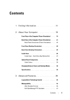 3
3 -
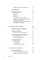 4
4 -
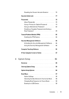 5
5 -
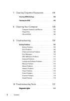 6
6 -
 7
7 -
8
-
9
-
10
-
11
-
12
-
13
-
14
-
15
-
16
-
17
-
18
-
19
-
20
-
21
-
22
-
23
-
24
-
25
-
26
-
27
-
28
-
29
-
30
-
31
-
32
-
33
-
34
-
35
-
36
-
37
-
38
-
39
-
40
-
41
-
42
-
43
-
44
-
45
-
46
-
47
-
48
-
49
-
50
-
51
-
52
-
53
-
54
-
55
-
56
-
57
-
58
-
59
-
60
-
61
-
62
-
63
-
64
-
65
-
66
-
67
-
68
-
69
-
70
-
71
-
72
-
73
-
74
-
75
-
76
-
77
-
78
-
79
-
80
-
81
-
82
-
83
-
84
-
85
-
86
-
87
-
88
-
89
-
90
-
91
-
92
-
93
-
94
-
95
-
96
-
97
-
98
-
99
-
100
-
101
-
102
-
103
-
104
-
105
-
106
-
107
-
108
-
109
-
110
-
111
-
112
-
113
-
114
-
115
-
116
-
117
-
118
-
119
-
120
-
121
-
122
-
123
-
124
-
125
-
126
-
127
-
128
-
129
-
130
-
131
-
132
-
133
-
134
-
135
-
136
-
137
-
138
-
139
-
140
-
141
-
142
-
143
-
144
-
145
-
146
-
147
-
148
-
149
-
150
-
151
-
152
-
153
-
154
-
155
-
156
-
157
-
158
-
159
-
160
-
161
-
162
-
163
-
164
-
165
-
166
-
167
-
168
-
169
-
170
-
171
-
172
-
173
-
174
-
175
-
176
-
177
-
178
-
179
-
180
-
181
-
182
-
183
-
184
-
185
-
186
-
187
-
188
-
189
-
190
-
191
-
192
-
193
-
194
-
195
-
196
-
197
-
198
-
199
-
200
-
201
-
202
-
203
-
204
-
205
-
206
-
207
-
208
-
209
-
210
-
211
-
212
-
213
-
214
-
215
-
216
-
217
-
218
-
219
-
220
-
221
-
222
-
223
-
224
-
225
-
226
-
227
-
228
-
229
-
230
-
231
-
232
-
233
-
234
-
235
-
236
-
237
-
238
-
239
-
240
-
241
-
242
-
243
-
244
-
245
-
246
-
247
-
248
-
249
-
250
-
251
-
252
-
253
-
254
-
255
-
256
-
257
-
258
-
259
-
260
-
261
-
262
-
263
-
264
-
265
-
266
-
267
-
268
-
269
-
270
-
271
-
272
-
273
-
274
-
275
-
276
-
277
-
278
-
279
-
280
-
281
-
282
-
283
-
284
-
285
-
286
-
287
-
288
-
289
-
290
-
291
-
292
-
293
-
294
-
295
-
296
-
297
-
298
-
299
-
300
-
301
-
302
-
303
-
304
-
305
-
306
-
307
-
308
-
309
-
310
-
311
-
312
-
313
-
314
-
315
-
316
 |
 |

www.dell.com | support.dell.com
Dell Precision™ T5400 User’s Guide
Model DCTA