Dell Vostro 1510 Service Manual - Page 10
Processor Module - memory
 |
View all Dell Vostro 1510 manuals
Add to My Manuals
Save this manual to your list of manuals |
Page 10 highlights
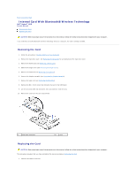
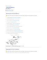
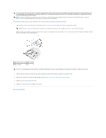
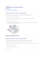
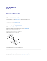
Back to Contents Page Processor Module Dell™ Vostro™ 1510 Service Manual Removing the Processor Module Replacing the Processor Module Removing the Processor Module CAUTION: Before you begin the following procedure, follow the safety instructions that shipped with your computer. 1. Follow the instructions in Before Working on Your Computer. 2. Loosen the two screws that secure the memory cover. (See Removing a Memory Module for an illustration of the memory cover.) 3. Slide the cover out of the compartment and set it aside. 4. Remove the fan (see Removing the Fan). 5. Remove the processor thermal-cooling assembly (see Removing the Processor Thermal-Cooling Assembly). NOTICE: To avoid damage to the processor, hold the screwdriver so that it is perpendicular to the processor when turning the cam screw. 6. To loosen the ZIF socket, use a small, flat-blade screwdriver and rotate the ZIF-socket cam screw counterclockwise until it comes to the cam stop. 1 ZIF-socket cam screw 2 ZIF socket NOTICE: To ensure maximum cooling for the processor, do not touch the heat transfer areas on the processor thermal-cooling assembly. The oils in your skin can reduce the heat transfer capability of the thermal pads. NOTICE: When removing the processor module, pull the module straight up. Be careful not to bend the pins on the processor module. 7. Lift the processor module from the ZIF socket. Replacing the Processor Module CAUTION: Before you begin the following procedure, follow the safety instructions that shipped with your computer. NOTICE: Do not touch the processor die. Press and hold the processor down on the substrate on which the die is mounted while turning the cam screw to prevent intermittent contact between the cam screw and processor.
-
 1
1 -
2
-
3
-
4
-
 5
5 -
 6
6 -
 7
7 -
 8
8 -
 9
9 -
 10
10 -
 11
11 -
 12
12 -
 13
13 -
 14
14 -
 15
15 -
16
-
17
-
18
-
19
-
20
-
21
-
22
-
23
-
24
-
25
-
26
-
27
-
28
-
29
-
30
-
31
-
32
-
33
-
34
-
35
-
36
-
37
-
38
-
39
-
40
-
41
-
42
-
43
-
44
-
45
-
46
-
47
-
48
-
49
-
50
-
51
-
52
-
53
-
54
-
55
-
56
-
57
-
58
-
59
-
60
-
61
-
62
 |
 |
