Dell Vostro 1510 Service Manual - Page 35
Replacing the Battery Latch Assembly
 |
View all Dell Vostro 1510 manuals
Add to My Manuals
Save this manual to your list of manuals |
Page 35 highlights
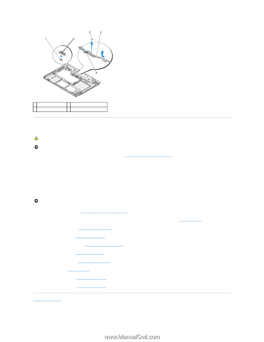
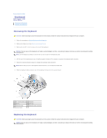
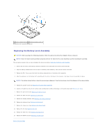
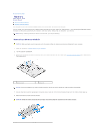
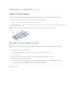
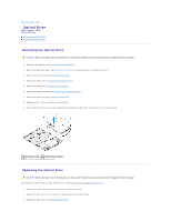
1 battery release button 2 alignment bracket screw (1) 3 battery latch assembly 4 spring Replacing the Battery Latch Assembly CAUTION: Before you begin the following procedure, follow the safety instructions that shipped with your computer. NOTICE: Ensure the battery latch assembly is properly oriented. The indent for the screw should face up when installing the assembly. This procedure assumes that you have completed the removal procedure Removing the Battery Latch Assembly. 1. Ensure that the battery latch spring is properly mounted on the guide post of the battery latch assembly. 2. Align the battery release button with the hole in the battery latch assembly, then press the button into place. 3. Replace the M2 x 3-mm screw that holds the battery release button in the battery latch assembly. 4. Align the guide post on the battery latch assembly with the slot on the base of the computer, then lower the latch assembly into place. NOTICE: The battery release button is keyed to ensure proper alignment. If you feel resistance, check the alignment of the release button. 5. Replace the system board (see Replacing the System Board Assembly). 6. Connect the cable that secures the internal card with Bluetooth wireless technology to the system board (see Replacing the Card). 7. Replace the optical drive (see Replacing the Optical Drive). 8. Replace the palm rest (see Replacing the Palm Rest). 9. Replace the display assembly (see Replacing the Display Assembly). 10. Replace the keyboard (see Replacing the Keyboard). 11. Replace the hinge cover (see Replacing the Hinge Cover). 12. Replace the fan (see Replacing the Fan). 13. Replace the hard drive (see Replacing the Hard Drive). 14. Replace the WLAN card (see Replacing a WLAN Card). Back to Contents Page
-
 1
1 -
2
-
3
-
4
-
5
-
6
-
7
-
8
-
9
-
10
-
11
-
12
-
13
-
14
-
15
-
16
-
17
-
18
-
19
-
20
-
21
-
22
-
23
-
24
-
25
-
26
-
27
-
28
-
29
-
 30
30 -
 31
31 -
 32
32 -
 33
33 -
 34
34 -
 35
35 -
 36
36 -
 37
37 -
 38
38 -
 39
39 -
 40
40 -
41
-
42
-
43
-
44
-
45
-
46
-
47
-
48
-
49
-
50
-
51
-
52
-
53
-
54
-
55
-
56
-
57
-
58
-
59
-
60
-
61
-
62
 |
 |