Dell Vostro 1510 Service Manual - Page 42
Palm Rest
 |
View all Dell Vostro 1510 manuals
Add to My Manuals
Save this manual to your list of manuals |
Page 42 highlights
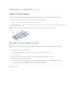
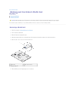
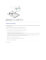
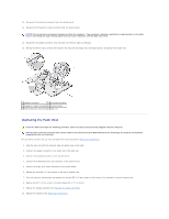
Back to Contents Page Palm Rest Dell™ Vostro™ 1510 Service Manual Removing the Palm Rest Replacing the Palm Rest Removing the Palm Rest CAUTION: Before you begin the following procedure, follow the safety instructions that shipped with your computer. 1. Follow the instructions in Before Working on Your Computer. 2. Remove the hard drive cover. See Removing the Hard Drive for an illustration of the hard drive cover. 3. Remove any cards or blanks installed in the ExpressCard slot and the 8-in- 1 card slot. 4. Remove the WLAN card (see Removing a WLAN Card). 5. Remove the hinge cover (see Removing the Hinge Cover). 6. Remove the keyboard (see Removing the Keyboard). 7. Remove the display assembly (see Removing the Display Assembly). 8. Remove the M2.5 x 5-mm screw labeled with a "P" from the fan. 9. Remove the fourteen M2.5 x 8-mm screws from the bottom of the computer. NOTE: The screw locations may vary slightly from the image shown below. 10. Turn the computer over and remove the three M2.5 x 5-mm screws that secure the top of the palm rest. 11. Disconnect the multimedia-button pad connector from the system board.
-
 1
1 -
2
-
3
-
4
-
5
-
6
-
7
-
8
-
9
-
10
-
11
-
12
-
13
-
14
-
15
-
16
-
17
-
18
-
19
-
20
-
21
-
22
-
23
-
24
-
25
-
26
-
27
-
28
-
29
-
30
-
31
-
32
-
33
-
34
-
35
-
36
-
 37
37 -
 38
38 -
 39
39 -
 40
40 -
 41
41 -
 42
42 -
 43
43 -
 44
44 -
 45
45 -
 46
46 -
 47
47 -
48
-
49
-
50
-
51
-
52
-
53
-
54
-
55
-
56
-
57
-
58
-
59
-
60
-
61
-
62
 |
 |