Dell Vostro 1510 Service Manual - Page 15
Display - inverter
 |
View all Dell Vostro 1510 manuals
Add to My Manuals
Save this manual to your list of manuals |
Page 15 highlights
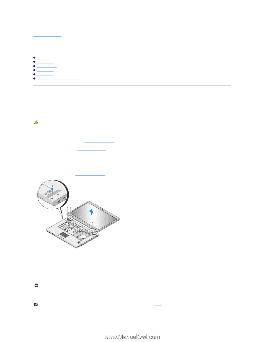
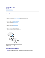
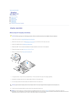
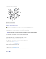
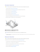
Back to Contents Page Display Dell™ Vostro™ 1510 Service Manual Display Assembly Display Bezel Display Inverter Display Panel Display Cable Camera and Microphone Assembly Display Assembly Removing the Display Assembly CAUTION: Before you begin the following procedure, follow the safety instructions that shipped with your computer. 1. Follow the instructions in Before Working on Your Computer. 2. Remove the hard drive cover. See Removing the Hard Drive for an illustration of the hard drive cover. 3. Remove the WLAN card (see Removing a WLAN Card). 4. Remove the M2.5 x 8-mm screw that attaches the display assembly to one corner of the computer. 5. Remove the hinge cover (see Removing the Hinge Cover). 6. Remove the keyboard (see Removing the Keyboard). 7. In sequential order, remove the four numbered M2.5 x 5-mm screws from the base of the display assembly. 8. Disconnect the display cable from the display cable connector on the system board. 9. Lift the display cable and antenna cables from beneath the tabs on the palm rest. NOTICE: Ensure that the display cable and the antenna cables do not get caught beneath the plastic tabs on the palm rest. 10. Gently tug on the antenna cables to remove them from underneath the palm rest. NOTE: The antenna cables are no longer attached to the WLAN card which you removed in step 3 of this procedure. Although the cables are unattached, they can be difficult to remove from underneath the palm rest. You may want to turn the computer upside down and remove the hard drive compartment cover and memory cover in order to have better access to the antenna cables.
-
 1
1 -
2
-
3
-
4
-
5
-
6
-
7
-
8
-
9
-
 10
10 -
 11
11 -
 12
12 -
 13
13 -
 14
14 -
 15
15 -
 16
16 -
 17
17 -
 18
18 -
 19
19 -
 20
20 -
21
-
22
-
23
-
24
-
25
-
26
-
27
-
28
-
29
-
30
-
31
-
32
-
33
-
34
-
35
-
36
-
37
-
38
-
39
-
40
-
41
-
42
-
43
-
44
-
45
-
46
-
47
-
48
-
49
-
50
-
51
-
52
-
53
-
54
-
55
-
56
-
57
-
58
-
59
-
60
-
61
-
62
 |
 |