Denon AVR-3312CI AVR3312CI_OwnersManual - Page 8
Connections, Important information
 |
UPC - 883795002042
View all Denon AVR-3312CI manuals
Add to My Manuals
Save this manual to your list of manuals |
Page 8 highlights
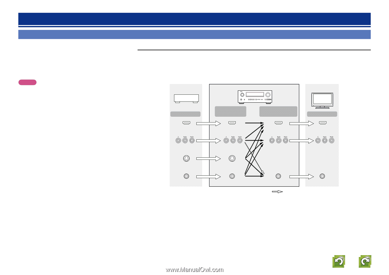
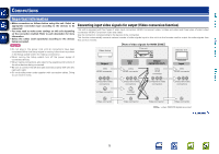
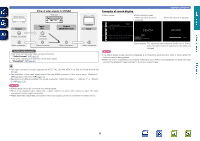
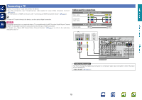
Basic version Advanced version Connections Important information • Make connections as follows before using this unit. Select an appropriate connection type according to the devices to be connected. • You may need to make some settings on this unit depending on the connection method. Refer to each description for more information. • Select the cables (sold separately) according to the devices being connected. NOTE • Do not plug in the power cord until all connections have been completed (When the Setup wizard is running, follow the instructions in the Setup wizard screen for making connections. ). • When running the Setup wizard, turn off the power supply of connected devices. • When making connections, also refer to the operating instructions of the other devices being connected. • Be sure to connect the left and right channels properly (left with left, right with right). • Do not bundle power cords together with connection cables. Doing so can result in noise. Converting input video signals for output (Video conversion function) This unit is equipped with four types of video input connectors (HDMI, Component video, S-Video and video) and three types of video output connectors (HDMI, Component video and video). Use the connectors corresponding to the devices to be connected. This function automatically converts various formats of video signals input to this unit into the formats used to output the video signals from this unit to a monitor. GFlow of video signals for MAIN ZONEH Video device This unit Monitor (TV) Output HDMI connector Input (IN) HDMI connector Output (MONITOR OUT) HDMI connector Input HDMI connector Component video connectors Component video connectors Component video connectors Component video connectors S-Video connector Video connector S-Video connector Video connector Video connector Video connector : when 480i/576i signals are input vSee overleaf Information 5
-
 1
1 -
2
-
 3
3 -
 4
4 -
 5
5 -
 6
6 -
 7
7 -
 8
8 -
 9
9 -
 10
10 -
 11
11 -
 12
12 -
 13
13 -
14
-
15
-
16
-
17
-
18
-
19
-
20
-
21
-
22
-
23
-
24
-
25
-
26
-
27
-
28
-
29
-
30
-
31
-
32
-
33
-
34
-
35
-
36
-
37
-
38
-
39
-
40
-
41
-
42
-
43
-
44
-
45
-
46
-
47
-
48
-
49
-
50
-
51
-
52
-
53
-
54
-
55
-
56
-
57
-
58
-
59
-
60
-
61
-
62
-
63
-
64
-
65
-
66
-
67
-
68
-
69
-
70
-
71
-
72
-
73
-
74
-
75
-
76
-
77
-
78
-
79
-
80
-
81
-
82
-
83
-
84
-
85
-
86
-
87
-
88
-
89
-
90
-
91
-
92
-
93
-
94
-
95
-
96
-
97
-
98
-
99
-
100
-
101
-
102
-
103
-
104
-
105
-
106
-
107
-
108
-
109
-
110
-
111
-
112
-
113
-
114
-
115
-
116
-
117
-
118
-
119
-
120
-
121
-
122
-
123
-
124
-
125
-
126
-
127
-
128
-
129
-
130
-
131
-
132
-
133
-
134
-
135
-
136
-
137
-
138
-
139
-
140
-
141
-
142
-
143
-
144
-
145
-
146
-
147
-
148
-
149
-
150
-
151
-
152
-
153
-
154
-
155
-
156
-
157
 |
 |