Epson Stylus Pro 7600 - UltraChrome Ink Service Manual - Page 115
Cleaning Mechanism
 |
View all Epson Stylus Pro 7600 - UltraChrome Ink manuals
Add to My Manuals
Save this manual to your list of manuals |
Page 115 highlights
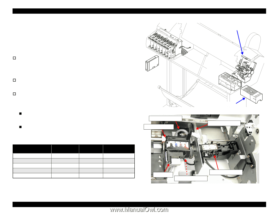
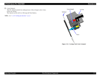
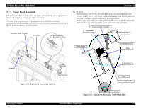
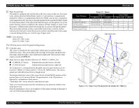
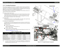
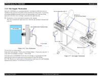
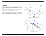
EPSON Stylus Pro 7600/9600 2.2.3 Cleaning Mechanism The cleaning mechanism in this printer is compatible with the cleaning mechanism in the Stylus Pro 5000/9000. The cleaning mechanism is located on the right side of the printer. The waste ink from the cleaning mechanism is channeled to the waste ink pad (Maintenance Tank) in the lower right side through the tube. The cleaning mechanism components are installed above the sub-frame and some are fixed on the main frame as shown below. † Pump assembly (head cleaner) When the head is in the capped position (valve closed), the pump motor creates a vacuum that sucks ink from the nozzles. This is used for removing ink from the nozzles and nozzle plate, initial ink charge, as well as cleaning. The waste ink flows through one small tube to the waste ink pads. † Head cleaner The head cleaner has felt on one side and rubber on the other, and is used to wipe or rub off ink and foreign materials from the nozzle surface. † Pump motor (stepping motor) The pump motor runs normally (the pump wheel turns clockwise as viewed from the pump wheel side) and reverses (the pump wheel turns counterclockwise) to execute the following functions: „ Clockwise rotation (CW): pump assembly drive for cleaning and so on (Suction, wiper setting) „ Counter clockwise rotation (CCW): Pump release, wiper reset, HD_SLIDE (head gap adjustment) cam drive. See "Platen Gap Adjustment Unit" (p.106). Table 2-6. Pump Drive Modes Suction Speed Name (Drive Mode) Low speed (IS5) Standard (IS4) High speed (IS3) Super-high speed (IS2) Super-high speed (IS1) Pump Wheel Revolving Speed 0.46 rev/sec 1.6 rev/sec 2.6 rev/sec 4.2 rev/sec 5 rev/sec Pump Wheel Motor Frequency Revolving Speed (2-2 phase conversion) 0.15 ml/sec 186 Hz 0.6 ml/sec 648 Hz 0.9 ml/sec 1053 Hz 1.1 ml/sec 1702 Hz 1.2 ml/sec 2026 Hz Note : The values for Motor Frequency above, given only for information, are obtained by 2-2 phase drive conversion with a drive system consisting of the pump wheel with P.C.D of φ 30.4 and motor gear with P.C.D of φ 6. Revision A Cleaning Mechanism (Maintenance ASSY) Maintenance Tank Figure 2-14. Cleaning Mechanism Components Pump assembly Flushing box Head cleaner CR Lock Pump motor Cap assembly Figure 2-15. Cleaning Mechanism Components Operating Principles Print Mechanism Components 115
-
 1
1 -
2
-
3
-
4
-
5
-
6
-
7
-
8
-
9
-
10
-
11
-
12
-
13
-
14
-
15
-
16
-
17
-
18
-
19
-
20
-
21
-
22
-
23
-
24
-
25
-
26
-
27
-
28
-
29
-
30
-
31
-
32
-
33
-
34
-
35
-
36
-
37
-
38
-
39
-
40
-
41
-
42
-
43
-
44
-
45
-
46
-
47
-
48
-
49
-
50
-
51
-
52
-
53
-
54
-
55
-
56
-
57
-
58
-
59
-
60
-
61
-
62
-
63
-
64
-
65
-
66
-
67
-
68
-
69
-
70
-
71
-
72
-
73
-
74
-
75
-
76
-
77
-
78
-
79
-
80
-
81
-
82
-
83
-
84
-
85
-
86
-
87
-
88
-
89
-
90
-
91
-
92
-
93
-
94
-
95
-
96
-
97
-
98
-
99
-
100
-
101
-
102
-
103
-
104
-
105
-
106
-
107
-
108
-
109
-
 110
110 -
 111
111 -
 112
112 -
 113
113 -
 114
114 -
 115
115 -
 116
116 -
 117
117 -
 118
118 -
 119
119 -
 120
120 -
121
-
122
-
123
-
124
-
125
-
126
-
127
-
128
-
129
-
130
-
131
-
132
-
133
-
134
-
135
-
136
-
137
-
138
-
139
-
140
-
141
-
142
-
143
-
144
-
145
-
146
-
147
-
148
-
149
-
150
-
151
-
152
-
153
-
154
-
155
-
156
-
157
-
158
-
159
-
160
-
161
-
162
-
163
-
164
-
165
-
166
-
167
-
168
-
169
-
170
-
171
-
172
-
173
-
174
-
175
-
176
-
177
-
178
-
179
-
180
-
181
-
182
-
183
-
184
-
185
-
186
-
187
-
188
-
189
-
190
-
191
-
192
-
193
-
194
-
195
-
196
-
197
-
198
-
199
-
200
-
201
-
202
-
203
-
204
-
205
-
206
-
207
-
208
-
209
-
210
-
211
-
212
-
213
-
214
-
215
-
216
-
217
-
218
-
219
-
220
-
221
-
222
-
223
-
224
-
225
-
226
-
227
-
228
-
229
-
230
-
231
-
232
-
233
-
234
-
235
-
236
-
237
-
238
-
239
-
240
-
241
-
242
-
243
-
244
-
245
-
246
-
247
-
248
-
249
-
250
-
251
-
252
-
253
-
254
-
255
-
256
-
257
-
258
-
259
-
260
-
261
-
262
-
263
-
264
-
265
-
266
-
267
-
268
-
269
-
270
-
271
-
272
-
273
-
274
-
275
-
276
-
277
-
278
-
279
-
280
-
281
-
282
-
283
-
284
-
285
-
286
-
287
-
288
-
289
-
290
-
291
-
292
-
293
-
294
-
295
-
296
-
297
-
298
-
299
-
300
-
301
-
302
-
303
-
304
-
305
-
306
-
307
-
308
-
309
-
310
-
311
-
312
-
313
-
314
-
315
-
316
-
317
-
318
-
319
-
320
-
321
-
322
-
323
-
324
-
325
-
326
-
327
-
328
-
329
-
330
-
331
-
332
-
333
-
334
-
335
-
336
 |
 |