Epson Stylus Pro 7600 - UltraChrome Ink Service Manual - Page 267

Cover Sensor ASSY Mounting Position Adjustment

Page 267 highlights

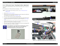
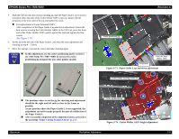
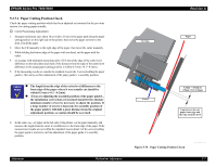
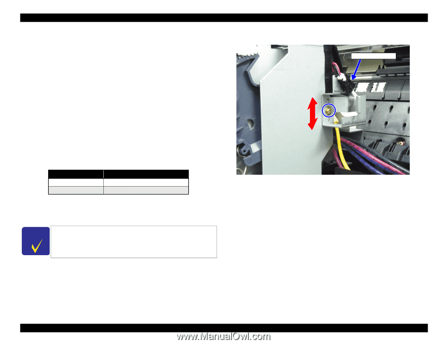
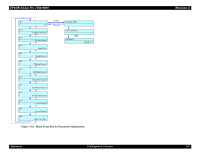
EPSON Stylus Pro 7600/9600 5.3.5 Cover Sensor ASSY Mounting Position Adjustment When removing/replacing the Cover Assembly or the Front Cover, verify the sensor operation using the Self-Diagnostic mode as described below. NOTE: For disassembly and assembly procedure, refer to "Cover Sensor ASSY" (p.197). 1. Remove the Tube cover. See "Cover Sensor ASSY" (p.197). 2. Start the Self-diagnostic Function: Power OFF → [Paper Feed ∆]+[Paper Feed ∇]+[Cut/Eject] → Power ON 3. Display "Test: Sensor": [SelecType >] → [Paper Feed ∇] x2 4. Display "Sen: Cover": [SelecType >] → [Paper Feed ∇] x1 5. Open and close the Front Cover, checking the LCD to make sure the message changes depending on the Front Cover position. Table 5-31. Cover Sensor Assembly Check Front Cover LCD Message Open Sen: Cover Open Close Sen: Cover Close 6. If the correct message does not appear or any other message appears, verify the Cover Sensor is installed correctly and check the operation again. CHECK P O IN T Acceptance Criterion: The timing for cover opening is such that there is no gap between the front cover and the printer body which permits entrance of your finger. Revision A Cover Sensor ASSY Figure 5-68. Adjusting the Cover Sensor ASSY Mounting Position Adjustment Mechanism Adjustment 267
  • 1
  • 2
  • 3
  • 4
  • 5
  • 6
  • 7
  • 8
  • 9
  • 10
  • 11
  • 12
  • 13
  • 14
  • 15
  • 16
  • 17
  • 18
  • 19
  • 20
  • 21
  • 22
  • 23
  • 24
  • 25
  • 26
  • 27
  • 28
  • 29
  • 30
  • 31
  • 32
  • 33
  • 34
  • 35
  • 36
  • 37
  • 38
  • 39
  • 40
  • 41
  • 42
  • 43
  • 44
  • 45
  • 46
  • 47
  • 48
  • 49
  • 50
  • 51
  • 52
  • 53
  • 54
  • 55
  • 56
  • 57
  • 58
  • 59
  • 60
  • 61
  • 62
  • 63
  • 64
  • 65
  • 66
  • 67
  • 68
  • 69
  • 70
  • 71
  • 72
  • 73
  • 74
  • 75
  • 76
  • 77
  • 78
  • 79
  • 80
  • 81
  • 82
  • 83
  • 84
  • 85
  • 86
  • 87
  • 88
  • 89
  • 90
  • 91
  • 92
  • 93
  • 94
  • 95
  • 96
  • 97
  • 98
  • 99
  • 100
  • 101
  • 102
  • 103
  • 104
  • 105
  • 106
  • 107
  • 108
  • 109
  • 110
  • 111
  • 112
  • 113
  • 114
  • 115
  • 116
  • 117
  • 118
  • 119
  • 120
  • 121
  • 122
  • 123
  • 124
  • 125
  • 126
  • 127
  • 128
  • 129
  • 130
  • 131
  • 132
  • 133
  • 134
  • 135
  • 136
  • 137
  • 138
  • 139
  • 140
  • 141
  • 142
  • 143
  • 144
  • 145
  • 146
  • 147
  • 148
  • 149
  • 150
  • 151
  • 152
  • 153
  • 154
  • 155
  • 156
  • 157
  • 158
  • 159
  • 160
  • 161
  • 162
  • 163
  • 164
  • 165
  • 166
  • 167
  • 168
  • 169
  • 170
  • 171
  • 172
  • 173
  • 174
  • 175
  • 176
  • 177
  • 178
  • 179
  • 180
  • 181
  • 182
  • 183
  • 184
  • 185
  • 186
  • 187
  • 188
  • 189
  • 190
  • 191
  • 192
  • 193
  • 194
  • 195
  • 196
  • 197
  • 198
  • 199
  • 200
  • 201
  • 202
  • 203
  • 204
  • 205
  • 206
  • 207
  • 208
  • 209
  • 210
  • 211
  • 212
  • 213
  • 214
  • 215
  • 216
  • 217
  • 218
  • 219
  • 220
  • 221
  • 222
  • 223
  • 224
  • 225
  • 226
  • 227
  • 228
  • 229
  • 230
  • 231
  • 232
  • 233
  • 234
  • 235
  • 236
  • 237
  • 238
  • 239
  • 240
  • 241
  • 242
  • 243
  • 244
  • 245
  • 246
  • 247
  • 248
  • 249
  • 250
  • 251
  • 252
  • 253
  • 254
  • 255
  • 256
  • 257
  • 258
  • 259
  • 260
  • 261
  • 262
  • 263
  • 264
  • 265
  • 266
  • 267
  • 268
  • 269
  • 270
  • 271
  • 272
  • 273
  • 274
  • 275
  • 276
  • 277
  • 278
  • 279
  • 280
  • 281
  • 282
  • 283
  • 284
  • 285
  • 286
  • 287
  • 288
  • 289
  • 290
  • 291
  • 292
  • 293
  • 294
  • 295
  • 296
  • 297
  • 298
  • 299
  • 300
  • 301
  • 302
  • 303
  • 304
  • 305
  • 306
  • 307
  • 308
  • 309
  • 310
  • 311
  • 312
  • 313
  • 314
  • 315
  • 316
  • 317
  • 318
  • 319
  • 320
  • 321
  • 322
  • 323
  • 324
  • 325
  • 326
  • 327
  • 328
  • 329
  • 330
  • 331
  • 332
  • 333
  • 334
  • 335
  • 336

EPSON Stylus Pro 7600/9600
Revision A
Adjustment
Mechanism Adjustment
267
5.3.5
Cover Sensor ASSY Mounting Position Adjustment
When removing/replacing the Cover Assembly or the Front Cover, verify the sensor
operation using the Self-Diagnostic mode as described below.
NOTE:
For disassembly and assembly procedure, refer to
“Cover Sensor ASSY”
(p.197)
.
1.
Remove the Tube cover.
See
“Cover Sensor ASSY”
(p.197)
.
2.
Start the Self-diagnostic Function:
Power OFF
[Paper Feed
]
+
[Paper Feed
]
+
[Cut/Eject]
Power ON
3.
Display “Test: Sensor”:
[SelecType >]
[Paper Feed
] x2
4.
Display “Sen: Cover”:
[SelecType >]
[Paper Feed
] x1
5.
Open and close the Front Cover, checking the LCD to make sure the message changes
depending on the Front Cover position.
6.
If the correct message does not appear or any other message appears, verify the Cover
Sensor is installed correctly and check the operation again.
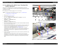
Figure 5-68.
Adjusting the Cover Sensor ASSY Mounting Position
Table 5-31.
Cover Sensor Assembly Check
Front Cover
LCD Message
Open
Sen: Cover
Open
Close
Sen: Cover
Close
C
H
E
C
K
P
O
I
N
T
Acceptance Criterion:
The timing for cover opening is such that there is no gap between
the front cover and the printer body which permits entrance of your
finger.
Cover Sensor ASSY