Epson Stylus Pro 7600 - UltraChrome Ink Service Manual - Page 119
Outline of Control Circuit Board
 |
View all Epson Stylus Pro 7600 - UltraChrome Ink manuals
Add to My Manuals
Save this manual to your list of manuals |
Page 119 highlights
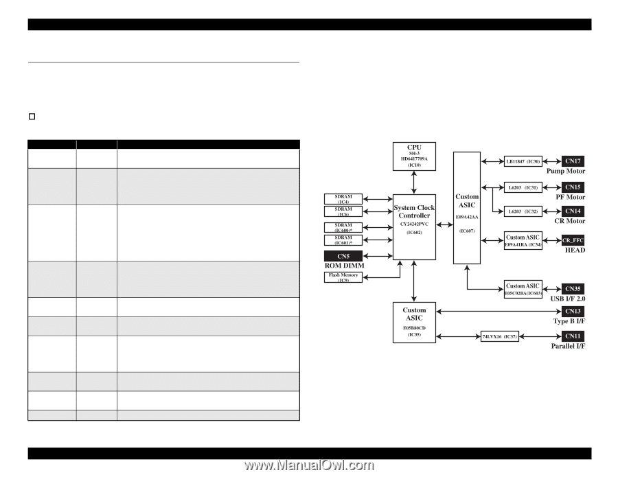
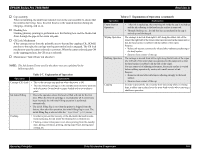
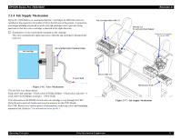
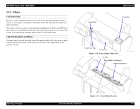
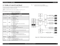
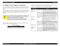
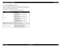
EPSON Stylus Pro 7600/9600 2.3 Outline of Control Circuit Board This section describes the operation of C472MAIN Board, which controls and drives the printer mechanism of Stylus Pro 7600/9600. NOTE: For details of each circuit, refer to Chapter 7 Appendix (p.281). † Explanation of major elements on C472MAIN Board Name/Code SH-3 HD6417709A CY24242PVC E09A42AA E05B80CD E09A41RA E05C02BA Flash Memory SD-RAM L6203 LB11847 Table 2-8. Major Elements Location Function IC10 32 bit RISC-CPU • Drive clock frequency = 100 MHz IC602 System clock controller • CPU clock • SDRAM clock • Clock for I/O control Custom ASIC 1. Print data processing IC607 • Rasterizer • Head drive control 2. Mechanism control (motors and solenoids) 3. Sensor control IC35 Custom ASIC • External I/O control IEEE1284 (bidirectional parallel) I/F Type-B port IC34 Custom ASIC • Head drive voltage waveform generation control IC603 Custom ASIC • USB-I/F (2.0) control IC9 IC4/6 IC600/601 Flash Memory (16Mbit) • For storage of control program (firmware) • Saving of various setting parameters and control information System memory * 128mbit x 16 IC31/32 PF/CR Motor Drivers IC • PWM constant current drive control IC30 Pump Motor Driver IC Note "*": Stylus Pro 7600: IC4/6 only (32MByte) Stylus Pro 9600: IC4/6 and IC600/601 (64MByte) Revision A Block01.eps Figure 2-20. C472MAIN Board-Circuit Block Diagram Operating Principles Outline of Control Circuit Board 119
-
 1
1 -
2
-
3
-
4
-
5
-
6
-
7
-
8
-
9
-
10
-
11
-
12
-
13
-
14
-
15
-
16
-
17
-
18
-
19
-
20
-
21
-
22
-
23
-
24
-
25
-
26
-
27
-
28
-
29
-
30
-
31
-
32
-
33
-
34
-
35
-
36
-
37
-
38
-
39
-
40
-
41
-
42
-
43
-
44
-
45
-
46
-
47
-
48
-
49
-
50
-
51
-
52
-
53
-
54
-
55
-
56
-
57
-
58
-
59
-
60
-
61
-
62
-
63
-
64
-
65
-
66
-
67
-
68
-
69
-
70
-
71
-
72
-
73
-
74
-
75
-
76
-
77
-
78
-
79
-
80
-
81
-
82
-
83
-
84
-
85
-
86
-
87
-
88
-
89
-
90
-
91
-
92
-
93
-
94
-
95
-
96
-
97
-
98
-
99
-
100
-
101
-
102
-
103
-
104
-
105
-
106
-
107
-
108
-
109
-
110
-
111
-
112
-
113
-
 114
114 -
 115
115 -
 116
116 -
 117
117 -
 118
118 -
 119
119 -
 120
120 -
 121
121 -
 122
122 -
 123
123 -
 124
124 -
125
-
126
-
127
-
128
-
129
-
130
-
131
-
132
-
133
-
134
-
135
-
136
-
137
-
138
-
139
-
140
-
141
-
142
-
143
-
144
-
145
-
146
-
147
-
148
-
149
-
150
-
151
-
152
-
153
-
154
-
155
-
156
-
157
-
158
-
159
-
160
-
161
-
162
-
163
-
164
-
165
-
166
-
167
-
168
-
169
-
170
-
171
-
172
-
173
-
174
-
175
-
176
-
177
-
178
-
179
-
180
-
181
-
182
-
183
-
184
-
185
-
186
-
187
-
188
-
189
-
190
-
191
-
192
-
193
-
194
-
195
-
196
-
197
-
198
-
199
-
200
-
201
-
202
-
203
-
204
-
205
-
206
-
207
-
208
-
209
-
210
-
211
-
212
-
213
-
214
-
215
-
216
-
217
-
218
-
219
-
220
-
221
-
222
-
223
-
224
-
225
-
226
-
227
-
228
-
229
-
230
-
231
-
232
-
233
-
234
-
235
-
236
-
237
-
238
-
239
-
240
-
241
-
242
-
243
-
244
-
245
-
246
-
247
-
248
-
249
-
250
-
251
-
252
-
253
-
254
-
255
-
256
-
257
-
258
-
259
-
260
-
261
-
262
-
263
-
264
-
265
-
266
-
267
-
268
-
269
-
270
-
271
-
272
-
273
-
274
-
275
-
276
-
277
-
278
-
279
-
280
-
281
-
282
-
283
-
284
-
285
-
286
-
287
-
288
-
289
-
290
-
291
-
292
-
293
-
294
-
295
-
296
-
297
-
298
-
299
-
300
-
301
-
302
-
303
-
304
-
305
-
306
-
307
-
308
-
309
-
310
-
311
-
312
-
313
-
314
-
315
-
316
-
317
-
318
-
319
-
320
-
321
-
322
-
323
-
324
-
325
-
326
-
327
-
328
-
329
-
330
-
331
-
332
-
333
-
334
-
335
-
336
 |
 |