Epson Stylus Pro 7600 - UltraChrome Ink Service Manual - Page 120
Outline of Power Supply Circuit Board
 |
View all Epson Stylus Pro 7600 - UltraChrome Ink manuals
Add to My Manuals
Save this manual to your list of manuals |
Page 120 highlights
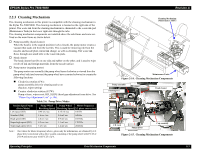
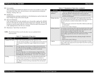
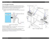
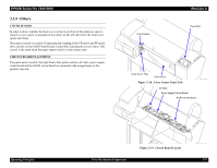
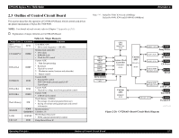
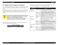
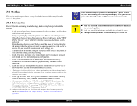
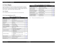
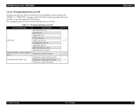
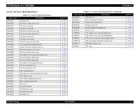
EPSON Stylus Pro 7600/9600 Revision A 2.4 Outline of Power Supply Circuit Board The 100 V AC power from the wall outlet is supplied via the power cable, an accessory of Stylus Pro 7600/9600, into the Inlet of the printer and to the Power Supply Circuit Board. The power switch constitutes a secondary power switch system. The secondary power switch system operates as follows: even with the power switch turned off, the Power Supply Circuit Board is operating by a slight power as long as the power cable is connected. C A U T IO N Even after the power switch is turned off, the Power Supply Circuit Board does not stop operating immediately, but power is kept on until the ink system ending sequence is completed. Do not disconnect the power cable or do not shut off power by turning off any power switch other than that on the printer. The Power Supply Circuit Board is equipped with a fuse for overcurrent protection. Table 2-9 below indicates the rating of the fuse: Table 2-9. Fuse Rating Input Voltage Range [V AC] Fuse Rating 100 +/- 10% 125 V AC / 6.3A There are three control signals between the C472MAIN Board and the Power Supply Circuit Board. Table below describes details of the control signals: Table 2-10. Control Signals between C472MAIN Board and Power Supply Board Signal Name Function REM_ON (MAIN→ Power Supply) Operating Turned ON/OFF by C472MAIN Board. • When these terminals are shorted, the drive system power supplies 28 VDC and 42 VDC are active. Off • When these terminals are open (= L), the drive system power supplies 28 VDC and 42 VDC are 0 VDC. • The 5 VDC power is not controlled with these terminals. AC_OFF (MAIN← Power Supply) Operating (= H) When each output from the Power Supply Circuit Board has become inactive because of turning off of the power switch or when the input voltage has dropped below the rated voltage value, "H" signal is sent to the C472MAIN Board. POW_ON/OFF (Panel / MAIN→Power Supply) Off (= L) Operating Off The power switch is turned on and the Power Supply Circuit Board Unit starts operating so that each output becomes active. "H" signal is sent to the C472MAIN Board. Connected to the power switch on the Panel Unit. • These terminals are shorted when the switch is ON. The Power Supply Circuit Board becomes active. • These terminals are open when the switch is OFF.The Power Supply Unit keeps operating for about ten and several seconds to a few minutes and then turns off. Operating Principles Outline of Power Supply Circuit Board 120
-
 1
1 -
2
-
3
-
4
-
5
-
6
-
7
-
8
-
9
-
10
-
11
-
12
-
13
-
14
-
15
-
16
-
17
-
18
-
19
-
20
-
21
-
22
-
23
-
24
-
25
-
26
-
27
-
28
-
29
-
30
-
31
-
32
-
33
-
34
-
35
-
36
-
37
-
38
-
39
-
40
-
41
-
42
-
43
-
44
-
45
-
46
-
47
-
48
-
49
-
50
-
51
-
52
-
53
-
54
-
55
-
56
-
57
-
58
-
59
-
60
-
61
-
62
-
63
-
64
-
65
-
66
-
67
-
68
-
69
-
70
-
71
-
72
-
73
-
74
-
75
-
76
-
77
-
78
-
79
-
80
-
81
-
82
-
83
-
84
-
85
-
86
-
87
-
88
-
89
-
90
-
91
-
92
-
93
-
94
-
95
-
96
-
97
-
98
-
99
-
100
-
101
-
102
-
103
-
104
-
105
-
106
-
107
-
108
-
109
-
110
-
111
-
112
-
113
-
114
-
 115
115 -
 116
116 -
 117
117 -
 118
118 -
 119
119 -
 120
120 -
 121
121 -
 122
122 -
 123
123 -
 124
124 -
 125
125 -
126
-
127
-
128
-
129
-
130
-
131
-
132
-
133
-
134
-
135
-
136
-
137
-
138
-
139
-
140
-
141
-
142
-
143
-
144
-
145
-
146
-
147
-
148
-
149
-
150
-
151
-
152
-
153
-
154
-
155
-
156
-
157
-
158
-
159
-
160
-
161
-
162
-
163
-
164
-
165
-
166
-
167
-
168
-
169
-
170
-
171
-
172
-
173
-
174
-
175
-
176
-
177
-
178
-
179
-
180
-
181
-
182
-
183
-
184
-
185
-
186
-
187
-
188
-
189
-
190
-
191
-
192
-
193
-
194
-
195
-
196
-
197
-
198
-
199
-
200
-
201
-
202
-
203
-
204
-
205
-
206
-
207
-
208
-
209
-
210
-
211
-
212
-
213
-
214
-
215
-
216
-
217
-
218
-
219
-
220
-
221
-
222
-
223
-
224
-
225
-
226
-
227
-
228
-
229
-
230
-
231
-
232
-
233
-
234
-
235
-
236
-
237
-
238
-
239
-
240
-
241
-
242
-
243
-
244
-
245
-
246
-
247
-
248
-
249
-
250
-
251
-
252
-
253
-
254
-
255
-
256
-
257
-
258
-
259
-
260
-
261
-
262
-
263
-
264
-
265
-
266
-
267
-
268
-
269
-
270
-
271
-
272
-
273
-
274
-
275
-
276
-
277
-
278
-
279
-
280
-
281
-
282
-
283
-
284
-
285
-
286
-
287
-
288
-
289
-
290
-
291
-
292
-
293
-
294
-
295
-
296
-
297
-
298
-
299
-
300
-
301
-
302
-
303
-
304
-
305
-
306
-
307
-
308
-
309
-
310
-
311
-
312
-
313
-
314
-
315
-
316
-
317
-
318
-
319
-
320
-
321
-
322
-
323
-
324
-
325
-
326
-
327
-
328
-
329
-
330
-
331
-
332
-
333
-
334
-
335
-
336
 |
 |