Epson Stylus Pro 7600 - UltraChrome Ink Service Manual - Page 212
Procedure for Adjustment Work, Adjustment Items
 |
View all Epson Stylus Pro 7600 - UltraChrome Ink manuals
Add to My Manuals
Save this manual to your list of manuals |
Page 212 highlights
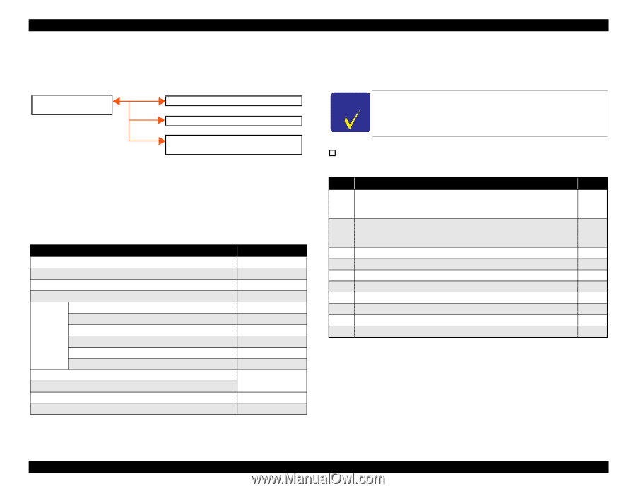
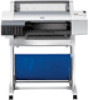
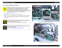
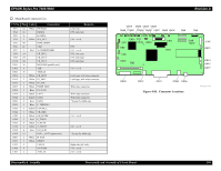
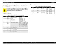
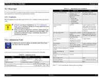
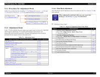
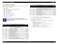
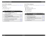
EPSON Stylus Pro 7600/9600 Revision A 5.1.3 Procedure for Adjustment Work Follow the specified steps by consulting "5.2 Self-diagnostic Function" (p.220) and "5.3 Mechanism Adjustment" (p.263) for adjustment items of each unit/part. Each Repair Item in "5.1.4 Adjustment Items" "5.2 Self-diagnostic Function" "5.3 Mechanism Adjustment" "5.1.5 Parameter Backup", "5.3.9 USB ID Writing", "1.4.5 Maintenance Mode 2", etc. 5.1.4 Adjustment Items Table 5-2 below indicates the parts replacement repair items for Stylus Pro 7600/9600 which requires adjustments. For actually performed part replacements, and disassembly and reassembly operations, the specified adjustment items should be performed in the sequence shown in the instructions. Table 5-2. Adjustment Items Repair Item (Page for Disassembly and Assembly) Print Head (p.171) MAIN Board (C472 MAIN) (p.207) CR Motor ASSY (p.180) PF Motor (p.185) Sensor P_EGDE Sensor ASSY (p.179) P_REAR Sensor ASSY (p.191) P_THICK Sensor/P_THICK Sensor_0.3 ASSY (p.190) CR Encoder Sensor ASSY (p.178) Cover Sensor ASSY (p.197) PF Encoder Sensor ASSY (p.186) Cutter Solenoid (p.177) Paper Guide L2 (p.168) Damper ASSY (p.173) Release Sensor (I/H Lever) (p.193) See for Adjustment p. 212 p. 213 p. 214 p. 214 p. 215 p. 215 p. 215 p. 215 p. 216 p. 216 p. 217 p. 217 p. 217 5.1.4.1 Print Head Adjustment Described below are the adjustment items to be made once the Print Head (p.171) has been replaced. CHECK P O IN T When replacing the print head with a new one, execute ink discharge ("Ink Blowing" on page 256) beforehand. † Adjustment items (steps): Table 5-3. Required Adjustment Items (Print Head) Step Adjustment Item 1 Clear the counter (Maintenance Mode2) (Power OFF →[Paper Source]+[Eject]+[Paper Feed] → Power ON) "HEAD" (Power OFF → [Paper Feed ∆]+[Paper Feed ∇]+[Cut/Eject] → Power ON) 2 Head Rank Input (including initial filling) 3 Head Nozzle Checking (Cleaning) 4 Head Slant Checking 5 Round Trip Print Position Adjustment (Bi-D Adjustment) 6 Round Trip Print Position (Bi-D Adjustment) Checking 7 Head Gap Adjustment (Uni-D Adjustment) 8 Test Pattern Printing 9 Leak check pattern printing See p. 70 p. 220 p. 233 p. 237 p. 246 p. 248 p. 252 p. 253 p. 255 p. 259 Adjustment Overview 212
-
 1
1 -
2
-
3
-
4
-
5
-
6
-
7
-
8
-
9
-
10
-
11
-
12
-
13
-
14
-
15
-
16
-
17
-
18
-
19
-
20
-
21
-
22
-
23
-
24
-
25
-
26
-
27
-
28
-
29
-
30
-
31
-
32
-
33
-
34
-
35
-
36
-
37
-
38
-
39
-
40
-
41
-
42
-
43
-
44
-
45
-
46
-
47
-
48
-
49
-
50
-
51
-
52
-
53
-
54
-
55
-
56
-
57
-
58
-
59
-
60
-
61
-
62
-
63
-
64
-
65
-
66
-
67
-
68
-
69
-
70
-
71
-
72
-
73
-
74
-
75
-
76
-
77
-
78
-
79
-
80
-
81
-
82
-
83
-
84
-
85
-
86
-
87
-
88
-
89
-
90
-
91
-
92
-
93
-
94
-
95
-
96
-
97
-
98
-
99
-
100
-
101
-
102
-
103
-
104
-
105
-
106
-
107
-
108
-
109
-
110
-
111
-
112
-
113
-
114
-
115
-
116
-
117
-
118
-
119
-
120
-
121
-
122
-
123
-
124
-
125
-
126
-
127
-
128
-
129
-
130
-
131
-
132
-
133
-
134
-
135
-
136
-
137
-
138
-
139
-
140
-
141
-
142
-
143
-
144
-
145
-
146
-
147
-
148
-
149
-
150
-
151
-
152
-
153
-
154
-
155
-
156
-
157
-
158
-
159
-
160
-
161
-
162
-
163
-
164
-
165
-
166
-
167
-
168
-
169
-
170
-
171
-
172
-
173
-
174
-
175
-
176
-
177
-
178
-
179
-
180
-
181
-
182
-
183
-
184
-
185
-
186
-
187
-
188
-
189
-
190
-
191
-
192
-
193
-
194
-
195
-
196
-
197
-
198
-
199
-
200
-
201
-
202
-
203
-
204
-
205
-
206
-
 207
207 -
 208
208 -
 209
209 -
 210
210 -
 211
211 -
 212
212 -
 213
213 -
 214
214 -
 215
215 -
 216
216 -
 217
217 -
218
-
219
-
220
-
221
-
222
-
223
-
224
-
225
-
226
-
227
-
228
-
229
-
230
-
231
-
232
-
233
-
234
-
235
-
236
-
237
-
238
-
239
-
240
-
241
-
242
-
243
-
244
-
245
-
246
-
247
-
248
-
249
-
250
-
251
-
252
-
253
-
254
-
255
-
256
-
257
-
258
-
259
-
260
-
261
-
262
-
263
-
264
-
265
-
266
-
267
-
268
-
269
-
270
-
271
-
272
-
273
-
274
-
275
-
276
-
277
-
278
-
279
-
280
-
281
-
282
-
283
-
284
-
285
-
286
-
287
-
288
-
289
-
290
-
291
-
292
-
293
-
294
-
295
-
296
-
297
-
298
-
299
-
300
-
301
-
302
-
303
-
304
-
305
-
306
-
307
-
308
-
309
-
310
-
311
-
312
-
313
-
314
-
315
-
316
-
317
-
318
-
319
-
320
-
321
-
322
-
323
-
324
-
325
-
326
-
327
-
328
-
329
-
330
-
331
-
332
-
333
-
334
-
335
-
336
 |
 |