Epson Stylus Pro 7600 - UltraChrome Ink Service Manual - Page 271
Paper Cutting Position Check
 |
View all Epson Stylus Pro 7600 - UltraChrome Ink manuals
Add to My Manuals
Save this manual to your list of manuals |
Page 271 highlights
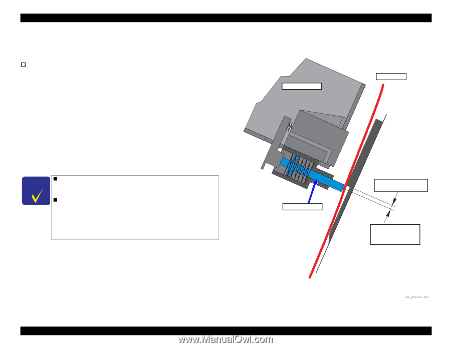
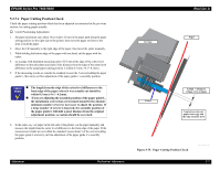
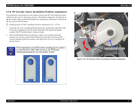
EPSON Stylus Pro 7600/9600 5.3.7.1 Paper Cutting Position Check Check the paper cutting position which has been adjusted as instructed in the previous section, by cutting paper actually. † Cutter Positioning Adjustment 1. Set paper (minimum size: about 10 cm wide x 20 cm) in the paper path along the paper setting position on the right side of the printer, then move the paper set lever to the front to hold the paper. 2. Move the CR manually to the right edge of the paper, then lower the cutter manually. 3. While holding the bottom edge of the paper with one hand, cut the paper with the cutter. 4. set a gauge with minimum measuring units of 0.5 mm at the edge of the cutter level difference on the sub-platen and check if the distance from the edge of the cutter level difference to the actual paper cutting position is within 0.5 mm (+0.1/-0.2mm). 5. If the measuring results are outside the standard, loosen the 3 screws holding the paper guide L, then carry out fine adjustment of the paper guide L's assembly position. CHECK P O IN T „ The length from the edge of the cutter level difference to the front edge of the paper where it was actually cut should be within 0.5 mm (+0.1/-0.2mm). „ If you are adjusting the assembly position of the paper guide L, the installation screws that are loosened should be the absolute minimum number of screws necessary to adjust the position. If a large number of screws is loosened, the assembly position of the paper guide L will shift a great distance from the original adjustment position, so caution should be exercised. 6. In the same way, set paper on the left side of the printer, cut the paper manually and measure the length from the cutter level difference to the front edge of the paper. If the measurement results are not within the standard, loosen about 3 of the screws holding the paper guide L and carry out fine adjustment of the paper guide L's assembly position. Adjustment Mechanism Adjustment Carriage Revision A Paper Cutter 0.3mm ∼ 0.5mm or 0.5mm (+0.1/-0.2mm) Gap between the cut paper front edge and the edge of cutter level Figure 5-75. Paper Cutting Position Check 271
-
 1
1 -
2
-
3
-
4
-
5
-
6
-
7
-
8
-
9
-
10
-
11
-
12
-
13
-
14
-
15
-
16
-
17
-
18
-
19
-
20
-
21
-
22
-
23
-
24
-
25
-
26
-
27
-
28
-
29
-
30
-
31
-
32
-
33
-
34
-
35
-
36
-
37
-
38
-
39
-
40
-
41
-
42
-
43
-
44
-
45
-
46
-
47
-
48
-
49
-
50
-
51
-
52
-
53
-
54
-
55
-
56
-
57
-
58
-
59
-
60
-
61
-
62
-
63
-
64
-
65
-
66
-
67
-
68
-
69
-
70
-
71
-
72
-
73
-
74
-
75
-
76
-
77
-
78
-
79
-
80
-
81
-
82
-
83
-
84
-
85
-
86
-
87
-
88
-
89
-
90
-
91
-
92
-
93
-
94
-
95
-
96
-
97
-
98
-
99
-
100
-
101
-
102
-
103
-
104
-
105
-
106
-
107
-
108
-
109
-
110
-
111
-
112
-
113
-
114
-
115
-
116
-
117
-
118
-
119
-
120
-
121
-
122
-
123
-
124
-
125
-
126
-
127
-
128
-
129
-
130
-
131
-
132
-
133
-
134
-
135
-
136
-
137
-
138
-
139
-
140
-
141
-
142
-
143
-
144
-
145
-
146
-
147
-
148
-
149
-
150
-
151
-
152
-
153
-
154
-
155
-
156
-
157
-
158
-
159
-
160
-
161
-
162
-
163
-
164
-
165
-
166
-
167
-
168
-
169
-
170
-
171
-
172
-
173
-
174
-
175
-
176
-
177
-
178
-
179
-
180
-
181
-
182
-
183
-
184
-
185
-
186
-
187
-
188
-
189
-
190
-
191
-
192
-
193
-
194
-
195
-
196
-
197
-
198
-
199
-
200
-
201
-
202
-
203
-
204
-
205
-
206
-
207
-
208
-
209
-
210
-
211
-
212
-
213
-
214
-
215
-
216
-
217
-
218
-
219
-
220
-
221
-
222
-
223
-
224
-
225
-
226
-
227
-
228
-
229
-
230
-
231
-
232
-
233
-
234
-
235
-
236
-
237
-
238
-
239
-
240
-
241
-
242
-
243
-
244
-
245
-
246
-
247
-
248
-
249
-
250
-
251
-
252
-
253
-
254
-
255
-
256
-
257
-
258
-
259
-
260
-
261
-
262
-
263
-
264
-
265
-
 266
266 -
 267
267 -
 268
268 -
 269
269 -
 270
270 -
 271
271 -
 272
272 -
 273
273 -
 274
274 -
 275
275 -
 276
276 -
277
-
278
-
279
-
280
-
281
-
282
-
283
-
284
-
285
-
286
-
287
-
288
-
289
-
290
-
291
-
292
-
293
-
294
-
295
-
296
-
297
-
298
-
299
-
300
-
301
-
302
-
303
-
304
-
305
-
306
-
307
-
308
-
309
-
310
-
311
-
312
-
313
-
314
-
315
-
316
-
317
-
318
-
319
-
320
-
321
-
322
-
323
-
324
-
325
-
326
-
327
-
328
-
329
-
330
-
331
-
332
-
333
-
334
-
335
-
336
 |
 |