HP StorageWorks 8/80 Brocade Converged Enhanced Ethernet Administrator's Guide - Page 134
CEE Priority Group Table defines each Priority Group ID PGID and its scheduling policy Strict
 |
View all HP StorageWorks 8/80 manuals
Add to My Manuals
Save this manual to your list of manuals |
Page 134 highlights
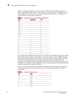
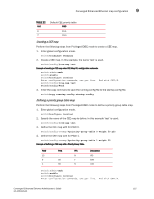
9 Converged Enhanced Ethernet map configuration CEE Priority Group Table defines each Priority Group ID (PGID) and its scheduling policy (Strict Priority versus DWRR, DWRR weight, relative priority), and partially defines the congestion control (PFC) configuration. There are 16 rows in the CEE Priority Group Table. Table 21 presents the default CEE Priority Group Table configuration. TABLE 21 PGID Default CEE Priority Group Table configuration Bandwidth% PFC 15.0 15.1 15.2 15.3 15.4 15.5 15.6 15.7 0 1 2 3 4 5 6 7 - N - N - N - N - N - N - N - N 0 N 0 N 0 N 0 N 0 N 0 N 0 N 0 N Strict Priority versus DWRR is derived directly from the PGID value. All PGIDs with prefix 15 receive Strict Priority scheduling policy and all PGIDs in the range 0 through 7 receive DWRR scheduling policy. Relative priority between Priority Group is exactly the ordering of entries listed in the table, with PGID 15.0 being highest priority and PGID 7 being lowest priority. Congestion control configuration is partially specified by toggling the PFC column On or Off. This provides only partial configuration of congestion control because the set of priorities mapped to the Priority Group is not known, which leads into the CEE Priority Table. CEE Priority Table defines each CoS mapping to Priority Group, and completes PFC configuration. There are eight rows in the CEE Priority Table. Table 22 shows the default CEE Priority Table configuration. TABLE 22 CoS Default CEE priority table PGID 0 15.6 1 15.7 2 15.5 3 15.4 4 15.3 5 15.2 114 Converged Enhanced Ethernet Administrator's Guide 53-1001346-01
-
 1
1 -
2
-
3
-
4
-
5
-
6
-
7
-
8
-
9
-
10
-
11
-
12
-
13
-
14
-
15
-
16
-
17
-
18
-
19
-
20
-
21
-
22
-
23
-
24
-
25
-
26
-
27
-
28
-
29
-
30
-
31
-
32
-
33
-
34
-
35
-
36
-
37
-
38
-
39
-
40
-
41
-
42
-
43
-
44
-
45
-
46
-
47
-
48
-
49
-
50
-
51
-
52
-
53
-
54
-
55
-
56
-
57
-
58
-
59
-
60
-
61
-
62
-
63
-
64
-
65
-
66
-
67
-
68
-
69
-
70
-
71
-
72
-
73
-
74
-
75
-
76
-
77
-
78
-
79
-
80
-
81
-
82
-
83
-
84
-
85
-
86
-
87
-
88
-
89
-
90
-
91
-
92
-
93
-
94
-
95
-
96
-
97
-
98
-
99
-
100
-
101
-
102
-
103
-
104
-
105
-
106
-
107
-
108
-
109
-
110
-
111
-
112
-
113
-
114
-
115
-
116
-
117
-
118
-
119
-
120
-
121
-
122
-
123
-
124
-
125
-
126
-
127
-
128
-
 129
129 -
 130
130 -
 131
131 -
 132
132 -
 133
133 -
 134
134 -
 135
135 -
 136
136 -
 137
137 -
 138
138 -
 139
139 -
140
-
141
-
142
-
143
-
144
-
145
-
146
-
147
-
148
-
149
-
150
-
151
-
152
-
153
-
154
-
155
-
156
-
157
-
158
-
159
-
160
-
161
-
162
 |
 |