HP StorageWorks 8/80 Brocade Converged Enhanced Ethernet Administrator's Guide - Page 51
Configuring DCBX
 |
View all HP StorageWorks 8/80 manuals
Add to My Manuals
Save this manual to your list of manuals |
Page 51 highlights
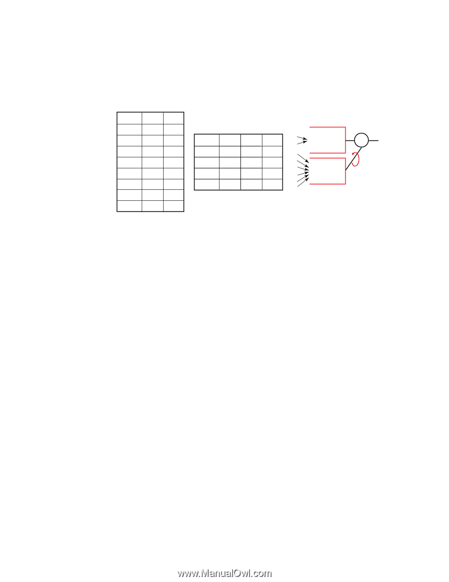
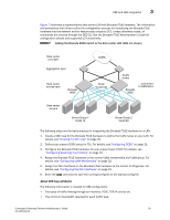
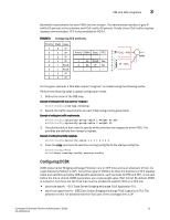
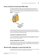
CEE and LAN integration 3 Bandwidth requirements for each PGID are then chosen. The administrator decides to give IP traffic 60 percent of the schedule and FCoE traffic 40 percent. Finally, since FCoE traffic requires lossless communication, PFC is also enabled for PGID 1. FIGURE 8 Configuring CEE attributes Priority PGID Desc 7 2 IP 6 2 IP 5 2 IP 4 2 IP 3 1 FCoE 2 1 FCoE 1 2 IP 0 2 IP Priority BW% Desc PFC - - - - 1 40 FCoE Yes 2 60 IP No - - - - 3 2 FCoE _ 40% 7 6 5 4 IP _ 60% 1 0 WRR For the given example, a CEE Map named "srvgroup" is created using the following syntax. Perform the following steps in global configuration mode. 1. Define the name of the CEE map Example of setting the CEE map name as "srvgroup". switch(config)#cee-map srvgroup 2. Specify the traffic requirements for each PGID using priority-group-table Example of setting two traffic requirements. switch(config)#priority-group-table 1 weight 40 pfc switch(config)#priority-group-table 2 weight 60 3. The priority-table is then used to specify which priorities are mapped to which PGID. The priorities are defined from lowest to highest. Example of setting the priority mappings. switch(config)#priority-table 2 2 1 1 2 2 2 2 4. Enter the copy command to save the running-config file to the startup-config file. switch(config)#end switch#copy running-config startup-config Configuring DCBX DCBX (Data Center Bridging eXchange Protocol) runs on CEE links and is an extension of the Link Layer Discovery Protocol (LLDP). The primary goal of DCBX is to allow the discovery of CEE-capable hosts and switches and allow CEE-specific parameters-such as those for ETS and PFC-to be sent before the link is shared. DCBX parameters use a type-length-value (TLV) format. By default, DCBX is turned on, but there are two TLVs that must be enabled to support FCoE on a CEE link: • dcbx-fcoe-app-tlv - IEEE Data Center Bridging eXchange FCoE Application TLV. • dcbx-fcoe-logical-link-tlv - IEEE Data Center Bridging eXchange FCoE Logical Link TLV. The presence of this TLV declares that the FCoE part of the converged link is UP. Converged Enhanced Ethernet Administrator's Guide 31 53-1001346-01
-
 1
1 -
2
-
3
-
4
-
5
-
6
-
7
-
8
-
9
-
10
-
11
-
12
-
13
-
14
-
15
-
16
-
17
-
18
-
19
-
20
-
21
-
22
-
23
-
24
-
25
-
26
-
27
-
28
-
29
-
30
-
31
-
32
-
33
-
34
-
35
-
36
-
37
-
38
-
39
-
40
-
41
-
42
-
43
-
44
-
45
-
 46
46 -
 47
47 -
 48
48 -
 49
49 -
 50
50 -
 51
51 -
 52
52 -
 53
53 -
 54
54 -
 55
55 -
 56
56 -
57
-
58
-
59
-
60
-
61
-
62
-
63
-
64
-
65
-
66
-
67
-
68
-
69
-
70
-
71
-
72
-
73
-
74
-
75
-
76
-
77
-
78
-
79
-
80
-
81
-
82
-
83
-
84
-
85
-
86
-
87
-
88
-
89
-
90
-
91
-
92
-
93
-
94
-
95
-
96
-
97
-
98
-
99
-
100
-
101
-
102
-
103
-
104
-
105
-
106
-
107
-
108
-
109
-
110
-
111
-
112
-
113
-
114
-
115
-
116
-
117
-
118
-
119
-
120
-
121
-
122
-
123
-
124
-
125
-
126
-
127
-
128
-
129
-
130
-
131
-
132
-
133
-
134
-
135
-
136
-
137
-
138
-
139
-
140
-
141
-
142
-
143
-
144
-
145
-
146
-
147
-
148
-
149
-
150
-
151
-
152
-
153
-
154
-
155
-
156
-
157
-
158
-
159
-
160
-
161
-
162
 |
 |