HP StorageWorks 8/80 Brocade Converged Enhanced Ethernet Administrator's Guide - Page 71
RSTP overview
 |
View all HP StorageWorks 8/80 manuals
Add to My Manuals
Save this manual to your list of manuals |
Page 71 highlights
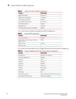
RSTP overview 5 6. Enable the guard root feature with the spanning-tree guard root command. The guard root feature provides a way to enforce the root bridge placement in the network. For detailed information, refer to"Enabling the guard root" on page 65. Note that this step is optional. All other switch ports connect to other switches and bridges are automatically placed in blocking mode. This does not apply to ports connected to workstations or PCs; these ports remain in the forwarding state. 7. Enter the copy command to save the running-config file to the startup-config file. When the spanning tree topology is completed, the network switches send and receive data only on the ports that are part of the spanning tree. Data received on ports that are not part of the spanning tree is blocked. NOTE Brocade recommends leaving other STP variables at their default values. For more information on STP, see "STP, RSTP, and MSTP configuration and management" on page 57. RSTP overview NOTE RSTP is designed to be compatible and interoperate with STP. However, the advantages of the RSTP fast reconvergence are lost when it interoperates with switches running STP. The IEEE 802.1w Rapid Spanning Tree Protocol (RSTP) standard is an evolution of the 802.1D STP standard. It provides rapid reconvergence following the failure of a switch, a switch port, or a LAN. It provides rapid reconvergence of edge ports, new root ports, and ports connected through point-to-point links. The RSTP interface states for every Layer 2 interface running RSTP are as follows: • Learning-The interface prepares to participate in frame forwarding. • Forwarding-The interface forwards frames. • Discarding-The interface discards frames. Note that the 802.1D disabled, blocking, and listening states are merged into the RSTP discarding state. Ports in the discarding state do not take part in the active topology and do not learn MAC addresses. Table 7 lists the interface state changes between STP and RSTP. TABLE 7 STP versus RSTP state comparison STP interface state RSTP interface state Is the interface included in the Is the interface learning MAC active topology? addresses? Disabled Discarding No No Blocking Discarding No No Listening Discarding Yes No Learning Learning Yes Yes Forwarding Forwarding Yes Yes Converged Enhanced Ethernet Administrator's Guide 51 53-1001346-01
-
 1
1 -
2
-
3
-
4
-
5
-
6
-
7
-
8
-
9
-
10
-
11
-
12
-
13
-
14
-
15
-
16
-
17
-
18
-
19
-
20
-
21
-
22
-
23
-
24
-
25
-
26
-
27
-
28
-
29
-
30
-
31
-
32
-
33
-
34
-
35
-
36
-
37
-
38
-
39
-
40
-
41
-
42
-
43
-
44
-
45
-
46
-
47
-
48
-
49
-
50
-
51
-
52
-
53
-
54
-
55
-
56
-
57
-
58
-
59
-
60
-
61
-
62
-
63
-
64
-
65
-
 66
66 -
 67
67 -
 68
68 -
 69
69 -
 70
70 -
 71
71 -
 72
72 -
 73
73 -
 74
74 -
 75
75 -
 76
76 -
77
-
78
-
79
-
80
-
81
-
82
-
83
-
84
-
85
-
86
-
87
-
88
-
89
-
90
-
91
-
92
-
93
-
94
-
95
-
96
-
97
-
98
-
99
-
100
-
101
-
102
-
103
-
104
-
105
-
106
-
107
-
108
-
109
-
110
-
111
-
112
-
113
-
114
-
115
-
116
-
117
-
118
-
119
-
120
-
121
-
122
-
123
-
124
-
125
-
126
-
127
-
128
-
129
-
130
-
131
-
132
-
133
-
134
-
135
-
136
-
137
-
138
-
139
-
140
-
141
-
142
-
143
-
144
-
145
-
146
-
147
-
148
-
149
-
150
-
151
-
152
-
153
-
154
-
155
-
156
-
157
-
158
-
159
-
160
-
161
-
162
 |
 |