HP StorageWorks 8/80 Brocade Converged Enhanced Ethernet Administrator's Guide - Page 92
HP StorageWorks 8/80 - SAN Switch Manual
 |
View all HP StorageWorks 8/80 manuals
Add to My Manuals
Save this manual to your list of manuals |
Page 92 highlights
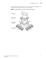
6 Link aggregation overview On each port, link aggregation control: • Maintains configuration information to control port aggregation. • Exchanges configuration information with other devices to form LAGs. • Attaches ports to and detaches ports from the aggregator when they join or leave a LAG. • Enables or disables an aggregator's frame collection and distribution functions. Each link in the Brocade FCoE hardware can be associated with a LAG; a link cannot be associated with more than one LAG. The process of adding and removing links to and from a LAG is controlled either statically, dynamically, or through LACP. Each LAG consists of the following components: • A MAC address that is different from the MAC addresses of the LAG's individual member links. • An interface index for each link to identify the link to neighboring devices. • An administrative key for each link. Only links having the same administrative key value can be aggregated into a LAG. On each link configured to use LACP, LACP automatically configures an administrative key value equal to the port-channel identification number. Figure 11 and Figure 12 show typical IP SAN configurations using LAGs. In a data center the Brocade 8000 switch fits into the top-of-the-rack use case where all the servers in a rack are connected to the Brocade 8000 switch through Twinax copper or optical fiber cable. The database server layer connects to the top-of-the-rack Brocade 8000 switch which is located in the network access layer. The Brocade 8000 switch connects to Layer 2/Layer 3 aggregation routers which provide access into the existing LAN. This connectivity is formed in a standard V-design or square-design. Both designs use the LAG as the uplink to provide redundancy and improved bandwidth. 72 Converged Enhanced Ethernet Administrator's Guide 53-1001346-01
-
 1
1 -
2
-
3
-
4
-
5
-
6
-
7
-
8
-
9
-
10
-
11
-
12
-
13
-
14
-
15
-
16
-
17
-
18
-
19
-
20
-
21
-
22
-
23
-
24
-
25
-
26
-
27
-
28
-
29
-
30
-
31
-
32
-
33
-
34
-
35
-
36
-
37
-
38
-
39
-
40
-
41
-
42
-
43
-
44
-
45
-
46
-
47
-
48
-
49
-
50
-
51
-
52
-
53
-
54
-
55
-
56
-
57
-
58
-
59
-
60
-
61
-
62
-
63
-
64
-
65
-
66
-
67
-
68
-
69
-
70
-
71
-
72
-
73
-
74
-
75
-
76
-
77
-
78
-
79
-
80
-
81
-
82
-
83
-
84
-
85
-
86
-
 87
87 -
 88
88 -
 89
89 -
 90
90 -
 91
91 -
 92
92 -
 93
93 -
 94
94 -
 95
95 -
 96
96 -
 97
97 -
98
-
99
-
100
-
101
-
102
-
103
-
104
-
105
-
106
-
107
-
108
-
109
-
110
-
111
-
112
-
113
-
114
-
115
-
116
-
117
-
118
-
119
-
120
-
121
-
122
-
123
-
124
-
125
-
126
-
127
-
128
-
129
-
130
-
131
-
132
-
133
-
134
-
135
-
136
-
137
-
138
-
139
-
140
-
141
-
142
-
143
-
144
-
145
-
146
-
147
-
148
-
149
-
150
-
151
-
152
-
153
-
154
-
155
-
156
-
157
-
158
-
159
-
160
-
161
-
162
 |
 |
