HP StorageWorks 8/80 Brocade Converged Enhanced Ethernet Administrator's Guide - Page 50
Creating the CEE map, two features: Enhanced Transmission Selection ETS and Priority Flow Control PFC.
 |
View all HP StorageWorks 8/80 manuals
Add to My Manuals
Save this manual to your list of manuals |
Page 50 highlights
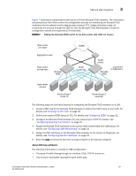
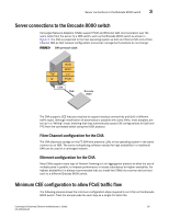
3 CEE and LAN integration • Which traffic type needs lossless behavior. Brocade uses CEE Maps to simplify the configuration of QoS and flow control. Users assign different priorities to different traffic types and enable lossless connectivity. A CEE map configures two features: Enhanced Transmission Selection (ETS) and Priority Flow Control (PFC). ETS is used to allocate bandwidth based on the different priority settings of the converged traffic. For example, users may want Inter-Process Communications (IPC) traffic to use as much bandwidth as needed, while LAN and SAN traffic share a designated percentage of the remaining bandwidth. ETS is used to manage the traffic priorities between traffic types by regulating flow and by assigning preset amounts of link bandwidth and relative priority to each application. 802.1q-tagged Ethernet frames contain a Priority Code Point (PCP) field, which describes the 802.1p class of service priority. This field indicates that a priority level that can be applied to different classes of traffic on a CEE link, using values ranging from 0 to 7. For example, a server administrator may assign FCoE traffic priority 3. Priorities are then grouped into Priority Group IDs (PGID), which are used by the switch to schedule frame forwarding. The Brocade FCoE hardware supports two types of scheduling: Strict Priority (SP) and Deficit Weighted Round Robin (DWRR). An SP scheduler drains all packets queued in the highest-priority queue before servicing lower-priority traffic classes. Use PGID 15 for strict priority scheduling. Use DWRR scheduling to facilitate controlled sharing of the network bandwidth. DWRR assigns each queue a weight, which is used to determine the frequency of frame forwarded for the queue. The round robin aspect of the scheduling allows each queue to be serviced in a set ordering, sending a limited amount of data before moving onto the next queue and cycling back to the highest priority queue after the lowest priority is serviced. PGIDs 0 to 7 can be used for DWRR scheduling. PFC is an enhancement to the current link-level flow control mechanism defined in IEEE 802.3X (PAUSE) so that it can operate individually on each priority. PFC is what enables lossless connectivity and is required for FCoE traffic. Creating the CEE map The first step is to define the types of traffic carried over the CEE network. As an example, servers in Figure 8 use the CEE network for both FCoE and IP. The administrator associates FCoE traffic with priorities 2 and 3 and IP traffic with priorities 0, 1, and 4-7. All the priorities used for IP traffic are grouped into a single Priority Group ID titled "PGID 1", and the priorities used for FCoE are grouped into "PGID 2". 30 Converged Enhanced Ethernet Administrator's Guide 53-1001346-01
-
 1
1 -
2
-
3
-
4
-
5
-
6
-
7
-
8
-
9
-
10
-
11
-
12
-
13
-
14
-
15
-
16
-
17
-
18
-
19
-
20
-
21
-
22
-
23
-
24
-
25
-
26
-
27
-
28
-
29
-
30
-
31
-
32
-
33
-
34
-
35
-
36
-
37
-
38
-
39
-
40
-
41
-
42
-
43
-
44
-
 45
45 -
 46
46 -
 47
47 -
 48
48 -
 49
49 -
 50
50 -
 51
51 -
 52
52 -
 53
53 -
 54
54 -
 55
55 -
56
-
57
-
58
-
59
-
60
-
61
-
62
-
63
-
64
-
65
-
66
-
67
-
68
-
69
-
70
-
71
-
72
-
73
-
74
-
75
-
76
-
77
-
78
-
79
-
80
-
81
-
82
-
83
-
84
-
85
-
86
-
87
-
88
-
89
-
90
-
91
-
92
-
93
-
94
-
95
-
96
-
97
-
98
-
99
-
100
-
101
-
102
-
103
-
104
-
105
-
106
-
107
-
108
-
109
-
110
-
111
-
112
-
113
-
114
-
115
-
116
-
117
-
118
-
119
-
120
-
121
-
122
-
123
-
124
-
125
-
126
-
127
-
128
-
129
-
130
-
131
-
132
-
133
-
134
-
135
-
136
-
137
-
138
-
139
-
140
-
141
-
142
-
143
-
144
-
145
-
146
-
147
-
148
-
149
-
150
-
151
-
152
-
153
-
154
-
155
-
156
-
157
-
158
-
159
-
160
-
161
-
162
 |
 |