HP StorageWorks 8/80 Brocade Converged Enhanced Ethernet Administrator's Guide - Page 47
Standard CEE Integrations and Configurations, In this Overview of standard CEE integrations
 |
View all HP StorageWorks 8/80 manuals
Add to My Manuals
Save this manual to your list of manuals |
Page 47 highlights
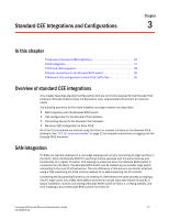
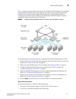
Chapter Standard CEE Integrations and Configurations 3 In this chapter •Overview of standard CEE integrations 27 •SAN Integration 27 •CEE and LAN integration 28 •Server connections to the Brocade 8000 switch 35 •Minimum CEE configuration to allow FCoE traffic flow 35 Overview of standard CEE integrations This chapter describes standard configurations that are commonly required for the Brocade FCoE hardware. Brocade believes these configurations cover approximately 90 percent of customer needs. The following scenarios for the newly installed converged network are described: • SAN integration with the Brocade 8000 switch • LAN configuration for the Brocade FCoE hardware • Connecting Servers to the Brocade FCoE hardware • Minimum CEE configuration to allow FCoE All of the CLI commands are entered using the Telnet or console interface on the Brocade FCoE hardware. See "CEE CLI command modes" on page 21 for complete instructions on logging into the Brocade FCoE hardware. SAN Integration FC SANs are typically deployed in a core-edge topology with servers connecting to edge switches in the fabric. Since the Brocade 8000 FC switching module operates with the same features and functionality of a regular FC switch, this topology is preserved when the Brocade 8000 switch is introduced into the fabric. The Brocade 8000 switch can be treated as just another edge switch connecting to the core FC infrastructure. The only difference is that servers are directly attached using a CNA supporting the FCoE protocol instead of an HBA supporting the FC protocol. Connecting the Brocade 8000 switch to an existing FC SAN follows the same process as adding a new FC edge switch into a SAN. Most SAN environments include redundant fabrics (A and B). A typical installation involves connecting a Brocade 8000 switch to Fabric A, verifying stability, and then installing a second Brocade 8000 switch into Fabric B. Converged Enhanced Ethernet Administrator's Guide 27 53-1001346-01
-
 1
1 -
2
-
3
-
4
-
5
-
6
-
7
-
8
-
9
-
10
-
11
-
12
-
13
-
14
-
15
-
16
-
17
-
18
-
19
-
20
-
21
-
22
-
23
-
24
-
25
-
26
-
27
-
28
-
29
-
30
-
31
-
32
-
33
-
34
-
35
-
36
-
37
-
38
-
39
-
40
-
41
-
 42
42 -
 43
43 -
 44
44 -
 45
45 -
 46
46 -
 47
47 -
 48
48 -
 49
49 -
 50
50 -
 51
51 -
 52
52 -
53
-
54
-
55
-
56
-
57
-
58
-
59
-
60
-
61
-
62
-
63
-
64
-
65
-
66
-
67
-
68
-
69
-
70
-
71
-
72
-
73
-
74
-
75
-
76
-
77
-
78
-
79
-
80
-
81
-
82
-
83
-
84
-
85
-
86
-
87
-
88
-
89
-
90
-
91
-
92
-
93
-
94
-
95
-
96
-
97
-
98
-
99
-
100
-
101
-
102
-
103
-
104
-
105
-
106
-
107
-
108
-
109
-
110
-
111
-
112
-
113
-
114
-
115
-
116
-
117
-
118
-
119
-
120
-
121
-
122
-
123
-
124
-
125
-
126
-
127
-
128
-
129
-
130
-
131
-
132
-
133
-
134
-
135
-
136
-
137
-
138
-
139
-
140
-
141
-
142
-
143
-
144
-
145
-
146
-
147
-
148
-
149
-
150
-
151
-
152
-
153
-
154
-
155
-
156
-
157
-
158
-
159
-
160
-
161
-
162
 |
 |