HP StorageWorks 8/80 Brocade Converged Enhanced Ethernet Administrator's Guide - Page 52
Configuring Spanning Tree Protocol, Configuring VLAN Membership
 |
View all HP StorageWorks 8/80 manuals
Add to My Manuals
Save this manual to your list of manuals |
Page 52 highlights
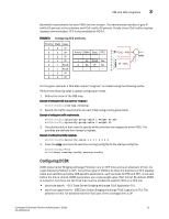
3 CEE and LAN integration To configure the TLVs for DCBX, perform the following steps in global configuration mode. 1. Set the protocol type to LLDP. switch(config)#protocol lldp 2. Activate the protocol. switch(conf-lldp)#no disable 3. Activate the TLV formats using the advertise command in Protocol LLDP Configuration Mode. switch(conf-lldp)#advertise dcbx-fcoe-app-tlv switch(conf-lldp)#advertise dcbx-fcoe-logical-link-tlv 4. Enter the copy command to save the running-config file to the startup-config file. switch(conf-lldp)#exit switch(config)#end switch#copy running-config startup-config Configuring Spanning Tree Protocol Spanning Tree Protocol is a mechanism to detect and avoid loops in Ethernet networks by establishing a fixed path between all the switches in a LAN. The Brocade FCoE hardware supports three spanning tree variations: Standard Spanning Tree (STP), Rapid Spanning Tree (RSTP), and Multiple Instance Spanning Tree (MSTP). It is best practice that an access layer switch, such as the Brocade 8000 switch, does not become the root switch. Changing the bridge or STP priority helps to ensure that this does not occur. The example below performed from the CEE CLI configures the Brocade 8000 switch for RSTP and sets the bridge priority to the highest value ensuring it will not become the root switch in an existing LAN. To configure RSTP, perform the following steps in global configuration mode. 1. Configure the Brocade 8000 switch for RSTP. switch(config)#protocol spanning-tree rstp 2. Set the bridge priority to the highest value so it does not become the root switch in an existing LAN. switch(conf-rstp)#bridge-priority 61440 3. Enter the copy command to save the running-config file to the startup-config file. switch(conf-rstp)#exit switch(config)#end switch#copy running-config startup-config Configuring VLAN Membership IEEE 802.1q Virtual LANs (VLANs) provide the capability to overlay the physical network with multiple virtual networks. VLANs allow network traffic isolation into separate virtual networks reducing the size of administrative and broadcast domains. A VLAN contains end stations that have a common set of requirements which can be in independent physical locations. You can group end stations in a VLAN even if they are not physically located in the same LAN segment. VLANs are typically associated with IP subnets and all the end stations in a particular IP subnet belong to the same VLAN. 32 Converged Enhanced Ethernet Administrator's Guide 53-1001346-01
-
 1
1 -
2
-
3
-
4
-
5
-
6
-
7
-
8
-
9
-
10
-
11
-
12
-
13
-
14
-
15
-
16
-
17
-
18
-
19
-
20
-
21
-
22
-
23
-
24
-
25
-
26
-
27
-
28
-
29
-
30
-
31
-
32
-
33
-
34
-
35
-
36
-
37
-
38
-
39
-
40
-
41
-
42
-
43
-
44
-
45
-
46
-
 47
47 -
 48
48 -
 49
49 -
 50
50 -
 51
51 -
 52
52 -
 53
53 -
 54
54 -
 55
55 -
 56
56 -
 57
57 -
58
-
59
-
60
-
61
-
62
-
63
-
64
-
65
-
66
-
67
-
68
-
69
-
70
-
71
-
72
-
73
-
74
-
75
-
76
-
77
-
78
-
79
-
80
-
81
-
82
-
83
-
84
-
85
-
86
-
87
-
88
-
89
-
90
-
91
-
92
-
93
-
94
-
95
-
96
-
97
-
98
-
99
-
100
-
101
-
102
-
103
-
104
-
105
-
106
-
107
-
108
-
109
-
110
-
111
-
112
-
113
-
114
-
115
-
116
-
117
-
118
-
119
-
120
-
121
-
122
-
123
-
124
-
125
-
126
-
127
-
128
-
129
-
130
-
131
-
132
-
133
-
134
-
135
-
136
-
137
-
138
-
139
-
140
-
141
-
142
-
143
-
144
-
145
-
146
-
147
-
148
-
149
-
150
-
151
-
152
-
153
-
154
-
155
-
156
-
157
-
158
-
159
-
160
-
161
-
162
 |
 |