HP StorageWorks 8/80 Brocade Converged Enhanced Ethernet Administrator's Guide - Page 49
About CEE map attributes, Creating the CEE map, Configuring DCBX
 |
View all HP StorageWorks 8/80 manuals
Add to My Manuals
Save this manual to your list of manuals |
Page 49 highlights
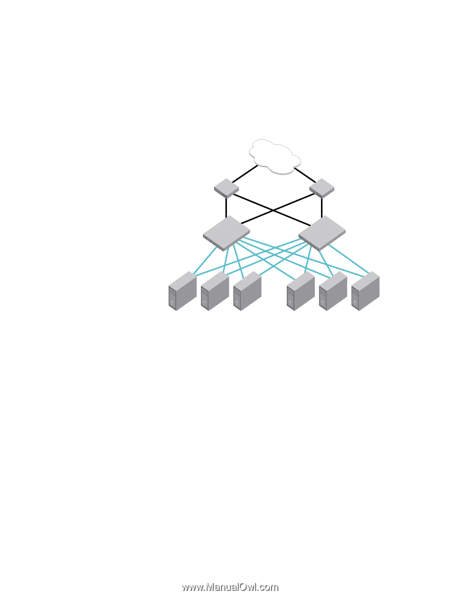
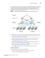
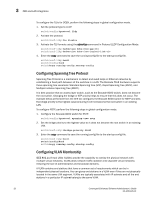
CEE and LAN integration 3 Figure 7 illustrates a representative data center LAN with Brocade FCoE hardware. The information and procedures that follow outline the configuration process for introducing the Brocade FCoE hardware into the network and for feature sets unique to CEE. Unless otherwise noted, all commands are entered through the CEE CLI. See the Brocade FCoE Administrator's Guide for configuration details and supported L2 functionality. FIGURE 7 Adding the Brocade 8000 switch to the data center LAN (SAN not shown) Data center core layer Aggregation layer Data center access layer Brocade 8000 CORE FCoE VLAN 100 VLAN trunks Brocade 8000 ...connected to SAN fabric Data center servers Server Group 1 VLAN 10 Server Group 2 VLAN 20 The following steps are the basic process for integrating the Brocade FCoE hardware on a LAN. 1. Create a CEE map for the Brocade FCoE hardware to define the traffic types on your LAN. For details, see"Creating the CEE map" on page 30. 2. Define your present DCBX setup for TLV. For details, see"Configuring DCBX" on page 31. 3. Configure the Brocade FCoE hardware for your present type of STP. For details, see "Configuring Spanning Tree Protocol" on page 32. 4. Assign the Brocade FCoE hardware to the correct VLAN membership and VLAN group. For details, see "Configuring VLAN Membership" on page 32. 5. Assign the CEE interfaces on the Brocade FCoE hardware to the correct VLAN groups. For details, see "Configuring the CEE Interfaces" on page 33. 6. Enter the copy command to save the running-config file to the startup-config file. About CEE map attributes The following information is needed for CEE configuration: • The types of traffic flowing through an interface, FCoE, TCP/IP, and so on. • The minimum bandwidth required for each traffic type. Converged Enhanced Ethernet Administrator's Guide 29 53-1001346-01
-
 1
1 -
2
-
3
-
4
-
5
-
6
-
7
-
8
-
9
-
10
-
11
-
12
-
13
-
14
-
15
-
16
-
17
-
18
-
19
-
20
-
21
-
22
-
23
-
24
-
25
-
26
-
27
-
28
-
29
-
30
-
31
-
32
-
33
-
34
-
35
-
36
-
37
-
38
-
39
-
40
-
41
-
42
-
43
-
 44
44 -
 45
45 -
 46
46 -
 47
47 -
 48
48 -
 49
49 -
 50
50 -
 51
51 -
 52
52 -
 53
53 -
 54
54 -
55
-
56
-
57
-
58
-
59
-
60
-
61
-
62
-
63
-
64
-
65
-
66
-
67
-
68
-
69
-
70
-
71
-
72
-
73
-
74
-
75
-
76
-
77
-
78
-
79
-
80
-
81
-
82
-
83
-
84
-
85
-
86
-
87
-
88
-
89
-
90
-
91
-
92
-
93
-
94
-
95
-
96
-
97
-
98
-
99
-
100
-
101
-
102
-
103
-
104
-
105
-
106
-
107
-
108
-
109
-
110
-
111
-
112
-
113
-
114
-
115
-
116
-
117
-
118
-
119
-
120
-
121
-
122
-
123
-
124
-
125
-
126
-
127
-
128
-
129
-
130
-
131
-
132
-
133
-
134
-
135
-
136
-
137
-
138
-
139
-
140
-
141
-
142
-
143
-
144
-
145
-
146
-
147
-
148
-
149
-
150
-
151
-
152
-
153
-
154
-
155
-
156
-
157
-
158
-
159
-
160
-
161
-
162
 |
 |