HP StorageWorks 8/80 Brocade Converged Enhanced Ethernet Administrator's Guide - Page 74
Configuring MSTP on Brocade FCoE hardware
 |
View all HP StorageWorks 8/80 manuals
Add to My Manuals
Save this manual to your list of manuals |
Page 74 highlights
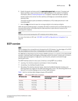
5 MSTP overview spanning tree instances. With MSTP you can have multiple forwarding paths for data traffic. A failure in one instance does not affect other instances. With MSTP, you are able to more effectively utilize the physical resources present in the network and achieve better load balancing of VLAN traffic. NOTE In MSTP mode, RSTP is automatically enabled to provide rapid convergence. Multiple switches must be configured consistently with the same MSTP configuration to participate in multiple spanning tree instances. A group of interconnected switches that have the same MSTP configuration is called an MSTP region. NOTE Brocade supports 16 MSTP instances and one MSTP region. MSTP introduces a hierarchical way of managing switch domains using regions. Switches that share common MSTP configuration attributes belong to a region. The MSTP configuration determines the MSTP region where each switch resides. The common MSTP configuration attributes are as follows: • Alphanumeric configuration name (32 bytes) • Configuration revision number (2 bytes) • 4096-element table that maps each of the VLANs to an MSTP instance Region boundaries are determined based on the above attributes. A multiple spanning tree instance is an RSTP instance that operates inside an MSTP region and determines the active topology for the set of VLANs mapping to that instance. Every region has a common internal spanning tree (CIST) that forms a single spanning tree instance that includes all the switches in the region. The difference between the CIST instance and the MSTP instance is that the CIST instance operates across the MSTP region and forms a loop-free topology across regions, while the MSTP instance operates only within a region. The CIST instance can operate using RSTP if all the switches across the regions support RSTP. However, if any of the switches operate using 802.1D STP, the CIST instance reverts to 802.1D. Each region is viewed logically as a single STP/RSTP bridge to other regions. Configuring MSTP on Brocade FCoE hardware The basic process for configuring MSTP on your Brocade FCoE hardware is as follows. 1. Enter Global Configuration mode. 2. Enable MSTP using the global protocol spanning-tree command. For more details see "Enabling STP, RSTP, or MSTP" on page 57. switch(config)#protocol spanning-tree mstp 3. Specify the region name using the region region_name command. For more details see "Specifying a name for an MSTP region" on page 62. switch(conf-mstp)#region brocade1 4. Specify the revision number using the revision command. For more details see "Specifying a revision number for an MSTP configuration" on page 62. switch(conf-mstp)#revision 1 54 Converged Enhanced Ethernet Administrator's Guide 53-1001346-01
-
 1
1 -
2
-
3
-
4
-
5
-
6
-
7
-
8
-
9
-
10
-
11
-
12
-
13
-
14
-
15
-
16
-
17
-
18
-
19
-
20
-
21
-
22
-
23
-
24
-
25
-
26
-
27
-
28
-
29
-
30
-
31
-
32
-
33
-
34
-
35
-
36
-
37
-
38
-
39
-
40
-
41
-
42
-
43
-
44
-
45
-
46
-
47
-
48
-
49
-
50
-
51
-
52
-
53
-
54
-
55
-
56
-
57
-
58
-
59
-
60
-
61
-
62
-
63
-
64
-
65
-
66
-
67
-
68
-
 69
69 -
 70
70 -
 71
71 -
 72
72 -
 73
73 -
 74
74 -
 75
75 -
 76
76 -
 77
77 -
 78
78 -
 79
79 -
80
-
81
-
82
-
83
-
84
-
85
-
86
-
87
-
88
-
89
-
90
-
91
-
92
-
93
-
94
-
95
-
96
-
97
-
98
-
99
-
100
-
101
-
102
-
103
-
104
-
105
-
106
-
107
-
108
-
109
-
110
-
111
-
112
-
113
-
114
-
115
-
116
-
117
-
118
-
119
-
120
-
121
-
122
-
123
-
124
-
125
-
126
-
127
-
128
-
129
-
130
-
131
-
132
-
133
-
134
-
135
-
136
-
137
-
138
-
139
-
140
-
141
-
142
-
143
-
144
-
145
-
146
-
147
-
148
-
149
-
150
-
151
-
152
-
153
-
154
-
155
-
156
-
157
-
158
-
159
-
160
-
161
-
162
 |
 |