Honeywell HPFF12 Operation Manual
Honeywell HPFF12 Manual
 |
View all Honeywell HPFF12 manuals
Add to My Manuals
Save this manual to your list of manuals |
Honeywell HPFF12 manual content summary:
- Honeywell HPFF12 | Operation Manual - Page 1
HPFF12(E)/HPFF12CM(E) NOTIFICATION APPLIANCE CIRCUIT EXPANDER INSTALLATION & OPERATION MANUAL P/N 53576:B • ECN 10-0569 • 11/24/2010 - Honeywell HPFF12 | Operation Manual - Page 2
detectors, manual pull Guides for Proper Use of System Smoke Detectors, which are made available at no charge to all installing alarm signals and instruct them on power. If AC power fails, the system will operate from standby batteries only for a specified time and only if the batteries of service - Honeywell HPFF12 | Operation Manual - Page 3
Services Department if any problems are anticipated or encountered. Disconnect AC power and batteries and if not installed and used in accordance with the instruction manual may cause interference NOTIFIER®, ONYX®, ONYXWorks®, UniNet®, VeriFire®, and VIEW® are all registered trademarks of Honeywell - Honeywell HPFF12 | Operation Manual - Page 4
Your suggestion for how to correct/improve documentation Send email messages to: [email protected] Please note this email address is for documentation feedback only. If you have any technical issues, please contact Technical Services. 4 HPFF12 NAC Expander - P/N 53576:B 11/24/2010 - Honeywell HPFF12 | Operation Manual - Page 5
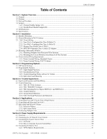
...13 Section 2: Installation ...17 2.1: Backbox Power Supply Requirements 48 6.1: Overview...48 6.2: Calculating the AC Branch Circuit Current...48 6.3: Calculating the System Current Draw ...49 6.3.1: Overview ...49 6.3.2: How to Calculate System Current Draw 50 6.4: Calculating the Battery - Honeywell HPFF12 | Operation Manual - Page 6
Table of Contents 6.4.2: Selecting and Locating Batteries ...51 6.5: NAC Circuit Loop Wiring Requirements...52 Appendix A: Device Compatibility 53 A.1: A.2.2: Gentex - 24 VDC ...54 A.2.3: Cooper-Wheelock ...55 A.2.4: Amseco ...57 A.2.5: Faraday...57 6 HPFF12 NAC Expander - P/N 53576:B 11/24/2010 - Honeywell HPFF12 | Operation Manual - Page 7
Underwriters Laboratories Standards • NFPA 72 National Fire Alarm Code Before proceeding, the installer should be familiar with the following documents. NFPA Standards NFPA 72 National Fire approval of the local Authority Having Jurisdiction (AHJ). HPFF12 NAC Expander - P/N 53576:B 11/24/2010 7 - Honeywell HPFF12 | Operation Manual - Page 8
8 HPFF12 NAC Expander - P/N 53576:B 11/24/2010 - Honeywell HPFF12 | Operation Manual - Page 9
installers requested to speed them through installation and servicing. The HPFF12 is a 12.0 A power supply that provides power for Notification Appliance Circuit (NAC) expansion to support Honeywell Fire Systems distributors.) HPFF12CM is a chassis-mount model that can fit two 12.0 AH batteries. - Honeywell HPFF12 | Operation Manual - Page 10
swapped in the field to accommodate Honeywell Fire Systems branded panels: Honeywell, Notifier, Gamewell FCI, Silent Knight, and FireLite Alarms. • 24 VDC remote power supply. • Outputs are completely power-limited. • Four output circuits: - Fully filtered power. - Four 24 VDC Class B (Style Y), or - Honeywell HPFF12 | Operation Manual - Page 11
35. 4. Wire the power supply circuits, referring to the options described in Section 4, "Trouble Supervision", on page 39 and the application examples in Section 5, "Applications", on page 42. 5. Connect the primary source wiring while observing the following: • HPFF12 and HPFF12CM: make certain the - Honeywell HPFF12 | Operation Manual - Page 12
components: a 24 VDC power supply and a Control circuit board. The HPFF12 models have an installed 12.0 A power supply. Jumpers are located on the control circuit board; see Figure 1.1, "Control Circuit Board". 1.4.1 Charger Disable Jumper (J1) The HPFF power supplies' battery charger capacity is - Honeywell HPFF12 | Operation Manual - Page 13
the Class B circuits. Otherwise, each NAC must have a trouble. 1.6 Specifications Refer to Section 1.1, "Control Circuit Board", on page 15 for terminal locations. Primary AC Power - TB1 (on 24 VDC power-supply circuit board) • HPFF12 and HPFF12CM: 120 VAC, 60 Hz, 5.0 A. • HPFF12E and HPFF12CME - Honeywell HPFF12 | Operation Manual - Page 14
disabled if battery voltage falls below 15 VDC. • Maximum charge current: 0.75 A. • Battery fuse (F1): 15 A, 32 V. • Maximum battery capacity: 26.0 AH. • Minimum battery capacity: 7.0 AH. • Power supply draws a maximum standby current of 75 mA from batteries. 14 HPFF12 NAC Expander - P/N 53576 - Honeywell HPFF12 | Operation Manual - Page 15
bottom): LED1 (Power On) LED2 (Auxiliary Trouble) LED3 (Battery Trouble) ED4 (Ground Fault Trouble) LED5 (Signal 4 Trouble) LED6 (Signal 3 Trouble) LED7 (Signal 2 Trouble) LED8 (Signal 1 Trouble) J1 Charger 1L2 2L1 2L2 3L1 3L2 4L1 4L2 HPFF812PCA.cdr HPFF12 NAC Expander - P/N 53576:B 11/24/2010 15 - Honeywell HPFF12 | Operation Manual - Page 16
System Overview Specifications HPFF12pca.wmf Figure 1.2 HPFF12 24 VDC Power Supply Circuit Board 16 HPFF12 NAC Expander - P/N 53576:B 11/24/2010 - Honeywell HPFF12 | Operation Manual - Page 17
for the devices to be installed. Sufficient knockouts are provided for wiring convenience. Select the appropriate knockout(s) and pull the conductors into the box. All wiring should be in accordance with the National and/or Local codes for fire alarm systems and power supplies. 2.1 Backbox Mounting - Honeywell HPFF12 | Operation Manual - Page 18
Installation Backbox Mounting 92udlscab.wm f Figure 2.1 Standard Cabinet: Dimensions 18 HPFF12 NAC Expander - P/N 53576:B 11/24/2010 - Honeywell HPFF12 | Operation Manual - Page 19
Backbox Mounting Installation Semi-Flush Mounting Do not recess box more than 3.875" into wall to avoid covering venting holes on top of box. 92udlsencl.wmf Figure 2.2 Standard Cabinet: Dimensions for Wall-mounting HPFF12 NAC Expander - P/N 53576:B 11/24/2010 19 - Honeywell HPFF12 | Operation Manual - Page 20
Installation 24-1/8" (61.28) (10.16) 4" 24" 11" (27.94) 11" (27.94) Height of mounting bolt after installation 1-7/8" (4.699) 2-5/8" (6.604) Four lower knockouts Inner 0.875" (2.22) Mounting holes 2 places NOTE: See EQ Series Install Sheet PN 53412 for door-mounting details and measurements - Honeywell HPFF12 | Operation Manual - Page 21
mounting plates as shown in Figure 2.6. 3. For the bottom-most chassis-mounting plate only, install four #8-32 keps nuts on the plate's studs as shown in Figure 2.6. This will properly space the battery well away from the backbox's mounting hardware. HPFF12 NAC Expander - P/N 53576:B 11/24/2010 21 - Honeywell HPFF12 | Operation Manual - Page 22
shown in Figure 2.7. 5. Install battery well by resting the bottom on top of the studs and securing the top with two #8-32 keps nuts as shown in Figure 2.7. Attach plug to transformer. (Ships unplugged.) hpff12cm-cable.wmf Figure 2.5 Attaching Transformer Plug 22 HPFF12 NAC Expander - P/N 53576 - Honeywell HPFF12 | Operation Manual - Page 23
-plate-mtg.wmf, hpff12cm-bottom-spacers.wmf Chassis-Mounting in FACP Cabinets Attach each chassismounting plate to backbox with two #8-32 kep nuts. Installation For the bottom chassis-mounting plate only: Install four #8-32 kep nuts onto studs where battery well is to be located. NOTE: This - Honeywell HPFF12 | Operation Manual - Page 24
of bottom row. hpff12cmmnt-eqdsize.wmf Secure top of battery well with two #8-32 kep nuts. Figure 2.7 HPFF12CM: Chassis-Mounting in Backbox (EQBB-D4 Shown) See power-limited wiring "HPFF12CM(E) Power-Limited Wiring, EQBB-D4 Backbox" on page 33. 24 HPFF12 NAC Expander - P/N 53576:B 11/24/2010 - Honeywell HPFF12 | Operation Manual - Page 25
in FACP Cabinets Installation hpff12cmmnt-eqcsize.wmf hpff12cmmnt-eqcsize.wmf Figure 2.9 One HPFF12CM Module in an EQBB-B4 Backbox Figure 2.8 Two HPFF12CM Modules in an EQBB-C4 Backbox See power-limited wiring "HPFF12CM(E) Power-Limited Wiring, EQBB-D4 Backbox" on page 33. HPFF12 NAC Expander - Honeywell HPFF12 | Operation Manual - Page 26
Installation NAC Circuit Wiring 2.3 NAC Circuit Wiring For wiring sizes, see Section 6.5, "NAC Circuit Loop Wiring Requirements". 2.3.1 Four NACs Configured for Class B (Style Y) Figure 2.10 shows four NACs configured for Class B (Style Y). • Trouble HPFF12 NAC Expander - P/N 53576:B 11/24/2010 - Honeywell HPFF12 | Operation Manual - Page 27
A (Style Z). • Trouble on NAC1 will illuminate LED1 SIG1 TRBL and LED2 SIG2 TRBL • Trouble on NAC2 will illuminate LED3 SIG3 TRBL and LED4 SIG4 TRBL Installation HPFF12NACClassA.wmf Horn Strobe Horn block. "T-tapping" is absolutely NOT ALLOWED. HPFF12 NAC Expander - P/N 53576:B 11/24/2010 27 - Honeywell HPFF12 | Operation Manual - Page 28
Installation NAC Circuit Wiring 2.3.3 Mixing Class B and Class A NACs Figure 2.12 shows two NACs configured for Class B (Style Y) and one NAC configured for Class A (Style Z). • Trouble on NAC1 will illuminate LED1 SIG1 TRBL • Trouble on NAC2 will illuminate LED2 SIG2 TRBL • Trouble on NAC3 will - Honeywell HPFF12 | Operation Manual - Page 29
support. The same gauge wire must be used if two conductors are connected to the same terminal of any terminal block. NOTE: Only use batteries Class A (Style Z) NACs with HPP31076 Adaptor NOTE: 1. Typical ELR's for new installations can be 3.9k or 4.7k ohm. 2. The same gauge wire must be used - Honeywell HPFF12 | Operation Manual - Page 30
Installation Mounting Addressable Modules 2.4 Mounting Addressable Modules The HPFF12 and the HPFF12E are designed to mount Honeywell Fire Systems addressable control or relay modules on the Control circuit board inside the power supply cabinet. This allows power possible in the HPFF12CM(E) units. - Honeywell HPFF12 | Operation Manual - Page 31
HPFF12CM(E) units when used in the large equipment enclosure. An optional multi-module chassis is available from Honeywell Fire Systems. See Section 2.5, "Power- knockouts may be used. For power-limited applications, use of conduit is optional. HPFF12 NAC Expander - P/N 53576:B 11/24/2010 31 - Honeywell HPFF12 | Operation Manual - Page 32
Installation Power-Limited Wiring Requirements 2.5.1 Power-Limited Wiring, Standard Chassis Relay Contacts Nonpower-limited HPFF812mntpwrlim.wmf AC Circuits Nonpower-limited Input Circuits Power-limited Specific Application: Power & SLC are power-limited Battery connections Nonpower-limited - Honeywell HPFF12 | Operation Manual - Page 33
: Maintain 0.25" in. vertical separation where power-limited and non-power-limited circuits appear to "cross" (e.g. Relay Contacts and AC Power, or HPP31076 NACs and battery connections). Figure 2.18 Power-Limited Wiring Example: EQBB-D4 with HPFF12CM(E) HPFF12 NAC Expander - P/N 53576:B 11/24/2010 - Honeywell HPFF12 | Operation Manual - Page 34
Installation Ground Stud Power-Limited Wiring Requirements Wire Nut HPFF12mntpwrlim-ACwir.wmf TB1 on 24 VDC circuit board L1 Ground L2 Line Neutral Ground Figure 2.19 Power-Limited Wiring Example: EQBB-D4 AC Wiring (Expanded) 34 HPFF12 NAC Expander - P/N 53576:B 11/24/2010 - Honeywell HPFF12 | Operation Manual - Page 35
3.2.4 for further details of TB2 immediate AC Fail and programmed no delay/delayed Trouble contacts. This switch works in conjunction with the initiating device signal input(s) and is silenced for the initiating device. Table 3.1 DIP Switch Settings HPFF12 NAC Expander - P/N 53576:B 11/24/2010 35 - Honeywell HPFF12 | Operation Manual - Page 36
are used to determine the input to output functions of the HPFF power supplies. The NAC outputs are programmed in pairs. DIP switches 1 and audible coded signals. The temporal generator feature is used to have the power supply generate a temporal audible code. The filtered feature is used to provide - Honeywell HPFF12 | Operation Manual - Page 37
activation can be a potential hazard and can cause confusion. The HPFF power supplies can be programmed to operate with a variety of manufacturers' devices. of TB2's AC FAIL and TROUBLE contacts and to set DIP switch 7 for a delay for UL 864 9th Edition compliance. HPFF12 NAC Expander - P/N 53576:B - Honeywell HPFF12 | Operation Manual - Page 38
outputs while keeping visual strobe activation. NOTE: See Section 5.1 and 5.2 for proper alarm input wiring when DIP switch 8 is programmed in the OFF position. 38 HPFF12 NAC Expander - P/N 53576:B 11/24/2010 - Honeywell HPFF12 | Operation Manual - Page 39
power supply • AC failure or brownout at the power supply • Battery failure (no battery or battery voltage less than 20.5 VDC) condition at the power supply • Battery charger failure on the power supply • Ground fault condition • +/- Reference Resistor NOTE: The trouble contacts AC FAIL and TROUBLE - Honeywell HPFF12 | Operation Manual - Page 40
the first 24 hours after initial power-up and the battery voltage had been discharged to a voltage between 20.5- 26.5 VDC. The BATT TRBL battery trouble LED may illuminate steady, after a certain delay during charging, to indicate the battery was discharged and may not support a full alarm load. The - Honeywell HPFF12 | Operation Manual - Page 41
yellow SIGTRBL LED(s) when all the troubles are cleared. This helps the installer or repair personnel to find the cause of intermittent troubles. The NAC Trouble Memory is permanently latched. To clear it, the AC must be cycled and the battery momentarily disconnected, or just press SW2 - Honeywell HPFF12 | Operation Manual - Page 42
NAC Circuits from a Single Source Notes for Figure 5.1: 1. When the power supply is in normal/standby state, a trouble will result in an open circuit condition on the FACP's NAC circuit ( terminal block. "T-tapping" is absolutely NOT ALLOWED. 42 HPFF12 NAC Expander - P/N 53576:B 11/24/2010 - Honeywell HPFF12 | Operation Manual - Page 43
Four NACs Alarm Polarity Shown Notes for Figure 5.2: 1. When the power supply is in normal/standby state, a trouble will result in an open circuit condition on the control module output at the terminal block. "T-tapping" is absolutely NOT ALLOWED. HPFF12 NAC Expander - P/N 53576:B 11/24/2010 43 - Honeywell HPFF12 | Operation Manual - Page 44
5.3 Wiring for Selective Silence Notes for Figure 5.3: 1. When the power supply is in normal/standby state, a trouble will result in an open circuit condition on the control module output circuit terminal block. "T-tapping" is absolutely NOT ALLOWED. 44 HPFF12 NAC Expander - P/N 53576:B 11/24/2010 - Honeywell HPFF12 | Operation Manual - Page 45
Install jumpers supplied with module hpff8-spl-6up.wmf Supervision Relay Alarm Polarity Shown Figure 5.4 Wiring for Split Alarm Mode Notes for Figure 5.4: 1. When the power supply is in normal/standby state, a trouble " is absolutely NOT ALLOWED. HPFF12 NAC Expander - P/N 53576:B 11/24/2010 45 - Honeywell HPFF12 | Operation Manual - Page 46
Connecting Multiple Units Two or more HPFF8 and/or HPFF12 units can be connected to each other to provide additional NAC extenders for a system; see wiring in Figures 5.5-5.10 and in the HPFF8 manual PN 53499. Maintain separation of power-limited and non-power limited wiring as discussed in Section - Honeywell HPFF12 | Operation Manual - Page 47
cannot be such that it creates a voltage drop > 2 VDC. Zline total =2V/(1 Unit + 1 ELR) Example: Zline total = 2V/(12.26 mA + (24-2)/4.7K) =118.1 ohms HPFF12 NAC Expander - P/N 53576:B 11/24/2010 47 - Honeywell HPFF12 | Operation Manual - Page 48
of AC branch circuit current required to operate the system 2. Calculating the power supply load current for non-alarm and alarm conditions and calculating the secondary (battery) load 3. Calculating the size of the batteries required to support the system if an AC loss occurs 4. Selecting the - Honeywell HPFF12 | Operation Manual - Page 49
power supply when primary power is applied, use the Calculation Column 1 in Table 6.4. The power supply must support a larger load current during an alarm condition. To calculate the fire alarm load on the power supply, use the Calculation Column 2 in Table 6.4. The secondary power source (batteries - Honeywell HPFF12 | Operation Manual - Page 50
the power supply must support during a non-alarm condition, with AC power applied • Calculation Column 2 - The primary AC supply current load that the power supply must support during an alarm condition, with AC power applied • Calculation Column 3 - The standby current drawn from the batteries in - Honeywell HPFF12 | Operation Manual - Page 51
Calculating the Battery Size Power Supply Requirements 6.4 Calculating the Battery Size Use Table 6.5 to calculate the total Standby and Alarm load in amperes hours (AH). This total load determines the battery size (in AH) required to support the power supply under the loss of AC. Complete Table - Honeywell HPFF12 | Operation Manual - Page 52
Power Supply Requirements NAC Circuit Loop Wiring Requirements 6.5 NAC Circuit Loop Wiring Requirements Make sure these requirements are met: NAC circuit cannot exceed 2.0 volts. NOTE: For loads smaller than 3 Amps, use the second calculation. 52 HPFF12 NAC Expander - P/N 53576:B 11/24/2010 - Honeywell HPFF12 | Operation Manual - Page 53
supported: • Control Modules - Single-input: Fire•Lite CMF-300, Notifier FCM-1, Notifier NC-100, Gamewell-FCI AOM2SF, ADT M300CADT, Johnson Controls M300CJ, Honeywell TC810N1013, Honeywell SP2C24115, SP2C24177 SpectrAlert Ceiling Mount Speaker Strobe HPFF12 NAC Expander - P/N 53576:B 11/24/2010 53 - Honeywell HPFF12 | Operation Manual - Page 54
) and / or markings (P=Plain, SP=Spanish, FR=French, B=Bi-lingual and PG=Portugese). (UL 864 9th Edition). A.2.2 Gentex - 24 VDC Use only 24 V devices with HPFF12 products. MODEL NUMBER & NOMENCLATURE (Gentex) GEC-24-15,GEC-24-30,GEC-24-60,GEC-24-75,GEC-24-110,GEC-24-15/75W Horn - Honeywell HPFF12 | Operation Manual - Page 55
Notification Appliances Device Compatibility A.2.3 Cooper-Wheelock Cooper-Wheelock Notification Use only 24 V devices with HPFF12 products. MODEL NUMBER & NOMENCLATURE (Cooper-Wheelock) 7002T-24 Horn with Strobe AES-DL1-WM-24-VF-R, AES-EL1-WM-24-VF-R Multi-Tone Signals AES- - Honeywell HPFF12 | Operation Manual - Page 56
E90-24MCC-FW, ET90-24MCC-FW, HS-24-R/W, MIZ-24S-R/W, RSS-24MCC-FW, NH-12/24R/W Cooper-Wheelock Speakers Use only 24 V devices with HPFF12 products. MODEL NUMBER & NOMENCLATURE (Cooper-Wheelock) E70, E70-R, E90, E90-W Speaker ET70, ET90 Speaker with Strobe E70-24MCW Speaker Strobe S25W, S70W Speaker - Honeywell HPFF12 | Operation Manual - Page 57
Notification Appliances Device Compatibility A.2.4 Amseco Use only 24 V devices with HPFF12 products. Compatible with the following: SH24W-153075, SAD24-153075, SAD24-75110, SL24W-75110, SL24C-3075110, SLB24-75 RSD24-153075, RSD24-75110, SH24W-75110, SH24W-3075110, - Honeywell HPFF12 | Operation Manual - Page 58
Device Compatibility Notification Appliances 58 HPFF12 NAC Expander - P/N 53576:B 11/24/2010 - Honeywell HPFF12 | Operation Manual - Page 59
(see AC loss) C cabinet 17, 21 dimensions 18, 19, 20 Calculating AC branch circuit current 48 Battery Size 51 Power supply currents 48 System Current Draw 49, 50 Calculating fire alarm load 49 Calculating power supply requirements procedures 48 Charger Disable Jumper (J1) 12 chassis removing 17 - Honeywell HPFF12 | Operation Manual - Page 60
power supply (defined) 49 Selecting and Locating Batteries 51 Selective silence 44 Semi-flush Mounting 19, 27 SIGNAL 1, SIGNAL 2 40, 41 Silencing 38 Silencing, see Selective silence Six-circuit modules 53 Specifications 13-16 Split alarm 38 Split alarm mode 45 Standards 7 Standby load calculations - Honeywell HPFF12 | Operation Manual - Page 61
branch circuit 48 also see NAC wiring Connecting multiple units 46 Control Panel Circuit Board 15 NAC applications 42, 43 NACs 26, 27, 28 separating power-limited from non-power- limited circuits 31-34 Split alarm mode 45 System Sync 46 Wire specifications 13-16 Wiring size 52 - Honeywell HPFF12 | Operation Manual - Page 62
W-W Index 62 HPFF12 NAC Expander - P/N 53576:B 11/24/2010 - Honeywell HPFF12 | Operation Manual - Page 63
Connecticut facility and sold by it to its authorized Distributors shall be free, under normal use and service, from defects in material and workmanship for a period of thirty six months (36) months from EVENT OF A WARRANTY CLAIM. Warn-HL-08-2009.fm HPFF12 NAC Expander - P/N 53576:B 11/24/2010 63 - Honeywell HPFF12 | Operation Manual - Page 64
Automation and Control Solutions Honeywell Power Products 12 Clintonville Road Northford, CT 06472-1610 www.honeywellpower.com ® U.S. Registered Trademark © 2010 Honeywell International Inc. 53576 B. Rev. 11-10
-
 1
1 -
 2
2 -
 3
3 -
 4
4 -
 5
5 -
 6
6 -
 7
7 -
8
-
9
-
10
-
11
-
12
-
13
-
14
-
15
-
16
-
17
-
18
-
19
-
20
-
21
-
22
-
23
-
24
-
25
-
26
-
27
-
28
-
29
-
30
-
31
-
32
-
33
-
34
-
35
-
36
-
37
-
38
-
39
-
40
-
41
-
42
-
43
-
44
-
45
-
46
-
47
-
48
-
49
-
50
-
51
-
52
-
53
-
54
-
55
-
56
-
57
-
58
-
59
-
60
-
61
-
62
-
63
-
64
 |
 |

INSTALLATION & OPERATION MANUAL
HPFF12(E)/HPFF12CM(E)
NOTIFICATION APPLIANCE CIRCUIT EXPANDER
P/N 53576:B • ECN 10-0569 • 11/24/2010