Honeywell HPFF12 Operation Manual - Page 51
Calculating the Battery Size, 6.4.1 NFPA Battery Requirements
 |
View all Honeywell HPFF12 manuals
Add to My Manuals
Save this manual to your list of manuals |
Page 51 highlights
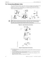
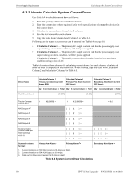
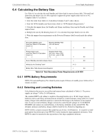
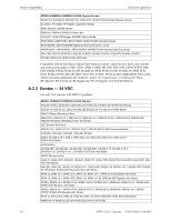
Calculating the Battery Size Power Supply Requirements 6.4 Calculating the Battery Size Use Table 6.5 to calculate the total Standby and Alarm load in amperes hours (AH). This total load determines the battery size (in AH) required to support the power supply under the loss of AC. Complete Table 6.5 as follows: 1. Enter the totals from Table 6.4, Calculation Columns 2 and 3 where shown. 2. Enter the NFPA Standby and Alarm times. Refer to "NFPA Battery Requirements." 3. Calculate the ampere hours for Standby and Alarm conditions, then sum the Standby and Alarm ampere hours. 4. Multiply the sum by the derating factor of 1.2 to calculate the proper battery size (in AH). 5. Write the ampere-hour requirements on the Protected Premises label located inside the cabinet door. Secondary Standby Load (total from Table 6.4 Calculation Column 3) [ ] Required Standby Time (24 or 60 hours) X [ ] = AH Primary Alarm Load Required Alarm Time (total from Table 6.4 Calculation (for 5 min., enter 0.084, Column 2) for 10 min., enter 0.168) [ ] X [ ] = AH Sum of Standby and Alarm Ampere Hours = AH Multiply by the Derating Factor* X 1.2 Battery Size, Total Ampere Hours Required = AH Table 6.5 Total Secondary Power Requirements at 24 VDC 6.4.1 NFPA Battery Requirements NFPA 72 Local and Propriety Fire Alarm Systems require 24 hours of standby power followed by 5 minutes in alarm 6.4.2 Selecting and Locating Batteries Select batteries that meet or exceed the total ampere hours calculated in Table 6.5. The power supply can charge 7 AH to 26 AH batteries. The standard HPFF wall cabinet is capable of housing batteries up to 18 AH. Larger capacity batteries can be used if they are housed in an external UL-Listed enclosure, along with a UL-Listed battery charger with sufficient capacity to restore the full charge to the batteries in the required time. To use an external battery charger, remove the control board's jumper at J1 CHARGER DISABLE and connect an external battery to the battery terminals on the control PCB. The alternate enclosure and battery charger shall be listed for Fire Protective Signaling use. HPFF12CM is a chassis mount (CM) model that can fit two 12AH batteries. It is used for a multipack option that allows up to four HPFF8/12 units mounted in large equipment enclosures. Note: HPFF12 cannot be mounted in the top position of the large equipment enclosure. HPFF12 NAC Expander - P/N 53576:B 11/24/2010 51
-
 1
1 -
2
-
3
-
4
-
5
-
6
-
7
-
8
-
9
-
10
-
11
-
12
-
13
-
14
-
15
-
16
-
17
-
18
-
19
-
20
-
21
-
22
-
23
-
24
-
25
-
26
-
27
-
28
-
29
-
30
-
31
-
32
-
33
-
34
-
35
-
36
-
37
-
38
-
39
-
40
-
41
-
42
-
43
-
44
-
45
-
 46
46 -
 47
47 -
 48
48 -
 49
49 -
 50
50 -
 51
51 -
 52
52 -
 53
53 -
 54
54 -
 55
55 -
 56
56 -
57
-
58
-
59
-
60
-
61
-
62
-
63
-
64
 |
 |