Honeywell HPFF12 Operation Manual - Page 39

Trouble Supervision, 4.1 Supervised Functions and Field Wiring, 4.2 Trouble Reporting

Page 39 highlights

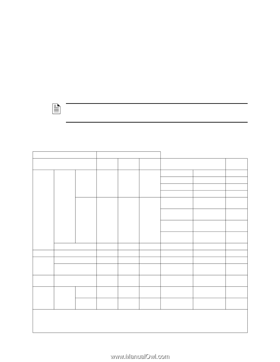
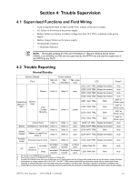
Section 4: Trouble Supervision 4.1 Supervised Functions and Field Wiring • Field-wiring fault (short or open) on the NAC outputs of the power supply • AC failure or brownout at the power supply • Battery failure (no battery or battery voltage less than 20.5 VDC) condition at the power supply • Battery charger failure on the power supply • Ground fault condition • +/- Reference Resistor NOTE: The trouble contacts AC FAIL and TROUBLE on TB2 and initiating device inputs SIGNAL1 and SIGNAL2 on TB3 are not supervised by the HPFF8, but are used for supervision of the HPFF8 by the FACP. 4.2 Trouble Reporting Normal/Standby Normal / Standby Trouble contacts Fault TB2: AC TB2: TB3: +IN & FAIL TROUBLE +OUT LED Reset? LED1: SIG1 TRBL Steady illumination Auto Present (Note 1) (Note 2) open LED2: SIG2 TRBL Steady illumination LED3: SIG3 TRBL Steady illumination Auto Auto LED4: SIG4 TRBL Steady illumination Auto Field Wiring (NAC & +/- REF) Short or Open Past (Trouble Memory) (Note 1) (Note 1) LED1: SIG1 TRBL closed LED2: SIG2 TRBL LED3: SIG3 TRBL Blink Blink Blink SW1 or Power cycle SW1 or Power cycle SW1 or Power cycle LED4: SIG4 TRBL Blink SW1 or Power cycle Ground Fault (Note 1) (Note 1) open LED5: GF TRBL Steady illumination Auto Battery No Battery or

  • 1
  • 2
  • 3
  • 4
  • 5
  • 6
  • 7
  • 8
  • 9
  • 10
  • 11
  • 12
  • 13
  • 14
  • 15
  • 16
  • 17
  • 18
  • 19
  • 20
  • 21
  • 22
  • 23
  • 24
  • 25
  • 26
  • 27
  • 28
  • 29
  • 30
  • 31
  • 32
  • 33
  • 34
  • 35
  • 36
  • 37
  • 38
  • 39
  • 40
  • 41
  • 42
  • 43
  • 44
  • 45
  • 46
  • 47
  • 48
  • 49
  • 50
  • 51
  • 52
  • 53
  • 54
  • 55
  • 56
  • 57
  • 58
  • 59
  • 60
  • 61
  • 62
  • 63
  • 64

HPFF12 NAC Expander —
P/N 53576:B
11/24/2010
39
Section 4: Trouble Supervision
4.1
Supervised Functions and Field Wiring
Field-wiring fault (short or open) on the NAC outputs of the power supply
AC failure or brownout at the power supply
Battery failure (no battery or battery voltage less than 20.5 VDC) condition at the power
supply
Battery charger failure on the power supply
Ground fault condition
+/- Reference Resistor
4.2
Trouble Reporting
Normal/Standby
NOTE:
The trouble contacts AC FAIL and TROUBLE on TB2 and initiating device inputs
SIGNAL1 and SIGNAL2 on TB3 are not supervised by the HPFF8, but are used for supervision of
the HPFF8 by the FACP.
Normal / Standby
Trouble contacts
Fault
TB2: AC
FAIL
TB2:
TROUBLE
TB3: +IN &
+OUT
LED
Reset?
Field Wiring
(NAC & +/-
REF)
Short or
Open
Present
(Note 1)
(Note 2)
open
LED1: SIG1 TRBL
Steady illumination
Auto
LED2: SIG2 TRBL
Steady illumination
Auto
LED3: SIG3 TRBL
Steady illumination
Auto
LED4: SIG4 TRBL
Steady illumination
Auto
Past
(Trouble
Memory)
(Note 1)
(Note 1)
closed
LED1: SIG1 TRBL
Blink
SW1 or
Power cycle
LED2: SIG2 TRBL
Blink
SW1 or
Power cycle
LED3: SIG3 TRBL
Blink
SW1 or
Power cycle
LED4: SIG4 TRBL
Blink
SW1 or
Power cycle
Ground Fault
(Note 1)
(Note 1)
open
LED5: GF TRBL
Steady illumination
Auto
Battery
No Battery or <20.5 VDC
(Note 1)
(Note 2)
open
LED6: BATT TRBL
Steady illumination
Auto
Battery
Charger
Fault
(Note 1)
(Note 2)
open
LED6: BATT TRBL
Blink
Auto
Battery not reach float
(Note 3)
(Note 1)
(Note 2)
open
LED6: BATT TRBL
Steady illumination
Auto
Auxiliary
output
Excessive load or short
(Note 1)
(Note 2)
open
LED7: AUX TRBL
Steady illumination
Auto
AC
Loss or
Brownout
No Delay
immediate
transfer
no delay
transfer
no delay
open
LED8: PWR ON
Blink
Auto
Delay
immediate
transfer
2hr delayed
transfer
2hr delayed
open
LED8: PWR ON t
Blink
Auto
1.
No transfer and COMM & N/C are shorted.
2.
The shorted contacts of COMM & N/C transfer to COM & N/O.
3.
A battery fail indication can also occur if there was an AC failure within the first 24 hours after initial power-up and the battery voltage had been
discharged to a voltage between 20.5- 26.5 VDC. The BATT TRBL battery trouble LED may illuminate steady, after a certain delay during
charging, to indicate the battery was discharged and may not support a full alarm load. The delay is based on operational conditions (time
remaining in the first 24 hours, time in stand-by, and time in alarm) and will extinguish if the battery charging has time to reach its float voltage.