Intel X5365 Design Guide - Page 24
Thermal Profile,
 |
UPC - 735858199292
View all Intel X5365 manuals
Add to My Manuals
Save this manual to your list of manuals |
Page 24 highlights
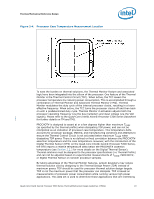
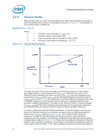
Thermal/Mechanical Reference Design 2.2.5 Thermal Profile The thermal profile is a linear line that defines the relationship between a processor's case temperature and its power consumption as shown in Figure 2-7. The equation of the thermal profile is defined as: Equation 2-1.y = ax + b Where: y = Processor case temperature, TCASE (°C) x = Processor power consumption (W) a = Case-to-ambient thermal resistance, ΨCA (°C/W) b = Processor local ambient temperature, TLA (°C) Figure 2-7. Thermal Profile Diagram TCASEMAX TCASEM AX @ P_PROFILE_MIN TCASE Thermal Profile P_PROFILE_MIN Power TDP The high end point of the Thermal Profile represents the processor's TDP and the associated maximum case temperature (TCASE_MAX). The lower end point of the Thermal Profile represents the power value (P_PROFILE_MIN) and the associated case temperature (TCASE_MAX@ P_PROFILE_MIN) for the lowest possible theoretical value of TCONTROL (see Section 2.2.6). The slope of the Thermal Profile line represents the caseto-ambient resistance of the thermal solution with the y-intercept being the local processor ambient temperature. The slope of the Thermal Profile is constant between P_PROFILE_MIN and TDP, which indicates that all frequencies of a processor defined by the Thermal Profile will require the same heatsink case-to-ambient resistance. In order to satisfy the Thermal Profile specification, a thermal solution must be at or below the Thermal Profile line for the given processor when its DTS temperature is greater than TCONTROL (refer to Section 2.2.6). The Thermal Profile allows the customers to make a trade-off between the thermal solution case-to-ambient resistance and the processor local ambient temperature that best suits their platform implementation (refer to Section 2.3.3). There can be multiple combinations of thermal solution case-to-ambient resistance and processor local ambient temperature that can meet a given Thermal Profile. If the case-to-ambient resistance and the local ambient 24 Quad-Core Intel® Xeon® Processor 5300 Series Thermal/Mechanical Design Guidelines (TMDG)
-
 1
1 -
2
-
3
-
4
-
5
-
6
-
7
-
8
-
9
-
10
-
11
-
12
-
13
-
14
-
15
-
16
-
17
-
18
-
 19
19 -
 20
20 -
 21
21 -
 22
22 -
 23
23 -
 24
24 -
 25
25 -
 26
26 -
 27
27 -
 28
28 -
 29
29 -
30
-
31
-
32
-
33
-
34
-
35
-
36
-
37
-
38
-
39
-
40
-
41
-
42
-
43
-
44
-
45
-
46
-
47
-
48
-
49
-
50
-
51
-
52
-
53
-
54
-
55
-
56
-
57
-
58
-
59
-
60
-
61
-
62
-
63
-
64
-
65
-
66
-
67
-
68
-
69
-
70
-
71
-
72
-
73
-
74
-
75
-
76
-
77
-
78
-
79
-
80
-
81
-
82
-
83
-
84
-
85
-
86
-
87
-
88
-
89
-
90
-
91
-
92
-
93
-
94
-
95
-
96
-
97
-
98
-
99
-
100
 |
 |
