Intel X5365 Design Guide - Page 25
TCONTROL Definition, Temperature, Tcontrol = -5
 |
UPC - 735858199292
View all Intel X5365 manuals
Add to My Manuals
Save this manual to your list of manuals |
Page 25 highlights
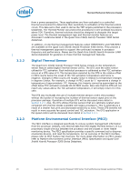
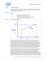
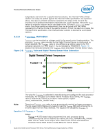
Thermal/Mechanical Reference Design temperature are known for a specific thermal solution, the Thermal Profile of that solution can easily be plotted against the Thermal Profile specification. As explained above, the case-to-ambient resistance represents the slope of the line and the processor local ambient temperature represents the y-axis intercept. Hence the TCASE values of a specific solution can be calculated at the TDP and P_PROFILE_MIN power levels. Once these points are determined, they can be joined by a line, which represents the Thermal Profile of the specific solution. If that line stays at or below the Thermal Profile specification, then that particular solution is deemed as a compliant solution. 2.2.6 TCONTROL Definition Figure 2-8. TCONTROL can be described as a trigger point for fan speed control implementation. The processor TCONTROL value provided by the Digital Thermal Sensor is relative and no longer absolute, the TCONTROL value is now defined as a relative value to the TCC activation set point (i.e. PECI Count = 0), as indicated by PROCHOT#. Figure 2-8 depicts the interaction between the TCONTROL value and Digital Thermal Sensor value. TCONTROL Value and Digital Thermal Sensor Value Interaction Digital Thermal Sensor Temperature 0 Tcontrol = -5 -10 Temperature -20 -30 -40 Time The value for TCONTROL is calibrated in manufacturing and configured for each processor individually. For the Quad-Core Intel® Xeon® Processor 5300 Series, the TCONTROL value is obtained by reading a processor model specific register (IA32_TEMPERATURE_TARGET MSR). Note: There is no TCONTROL_BASE value to sum as previously required on legacy processors. The fan speed control device only needs to read the TOFFSET MSR and compare this to the DTS value from the PECI interface. The equation for calculating TCONTROL is: Equation 2-2.TCONTROL = -TOFFSET Where: TOFFSET = A DTS-based value programmed into each processor during manufacturing that can be obtained by reading the IA32_TEMPERATURE_TARGET MSR. This is a static and a unique value. Refer to the Conroe and Woodcrest Processor Family BIOS Writer's Guide (BWG) for further details. Quad-Core Intel® Xeon® Processor 5300 Series Thermal/Mechanical Design Guidelines (TMDG) 25
-
 1
1 -
2
-
3
-
4
-
5
-
6
-
7
-
8
-
9
-
10
-
11
-
12
-
13
-
14
-
15
-
16
-
17
-
18
-
19
-
 20
20 -
 21
21 -
 22
22 -
 23
23 -
 24
24 -
 25
25 -
 26
26 -
 27
27 -
 28
28 -
 29
29 -
 30
30 -
31
-
32
-
33
-
34
-
35
-
36
-
37
-
38
-
39
-
40
-
41
-
42
-
43
-
44
-
45
-
46
-
47
-
48
-
49
-
50
-
51
-
52
-
53
-
54
-
55
-
56
-
57
-
58
-
59
-
60
-
61
-
62
-
63
-
64
-
65
-
66
-
67
-
68
-
69
-
70
-
71
-
72
-
73
-
74
-
75
-
76
-
77
-
78
-
79
-
80
-
81
-
82
-
83
-
84
-
85
-
86
-
87
-
88
-
89
-
90
-
91
-
92
-
93
-
94
-
95
-
96
-
97
-
98
-
99
-
100
 |
 |
