Intel X5365 Design Guide - Page 26
Thermal Profile Concepts for the Quad-Core Intel® Xeon® Processor 5300 Series
 |
UPC - 735858199292
View all Intel X5365 manuals
Add to My Manuals
Save this manual to your list of manuals |
Page 26 highlights
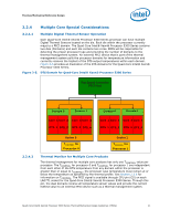
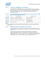
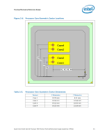
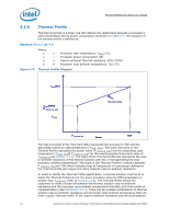
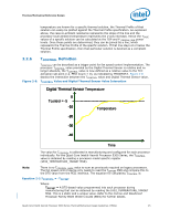
Thermal/Mechanical Reference Design Figure 2-9 depicts the interaction between the Thermal Profile and TCONTROL. Figure 2-9. TCONTROL and Thermal Profile Interaction TCASEM AX TCASE@DTS= TCONTROL TCASEM AX@ P_PROFILE_MIN ② ① Thermal Profile TCASE P_PROFILE_MIN Power TDP 2.2.7 2.2.7.1 Since TCONTROL is based on a processor DTS temperature value, an equivalent TCASE temperature must be determined to plot the TCASE @ TCONTROL point on the Thermal Profile graph. Location 1 on the Thermal Profile represents a TCASE value corresponding to P_PROFILE_MIN. Location 2 on the Thermal Profile represents a TCASE value corresponding to DTS = TCONTROL. If the DTS temperature is less than TCONTROL, then the case temperature is permitted to exceed the Thermal Profile, but the DTS temperature must remain at or below TCONTROL. The thermal solution for the processor must be able to keep the processor's TCASE at or below the TCASE values defined by the Thermal Profile between the TCASE_MAX @P_PROFILE_MINand TCASE_MAX points at the corresponding power levels. Refer to Section 2.3.1 for the implementation of the TCONTROL value in support of fan speed control (FSC) design to achieve better acoustic performance. Thermal Profile Concepts for the Quad-Core Intel® Xeon® Processor 5300 Series Dual Thermal Profile Concept for the Quad-Core Intel® Xeon® Processor X5300 Series The Quad-Core Intel® Xeon® Processor X5300 Series is designed to go into various form factors, including the volumetrically constrained 1U and custom blade form factors. Due to certain limitations of such form factors (i.e. airflow, thermal solution height), it is very challenging to meet the thermal requirements of the processor. To mitigate these form factor constraints, Intel has developed a dual Thermal Profile specification, shown in Figure 2-10. 26 Quad-Core Intel® Xeon® Processor 5300 Series Thermal/Mechanical Design Guidelines (TMDG)
-
 1
1 -
2
-
3
-
4
-
5
-
6
-
7
-
8
-
9
-
10
-
11
-
12
-
13
-
14
-
15
-
16
-
17
-
18
-
19
-
20
-
 21
21 -
 22
22 -
 23
23 -
 24
24 -
 25
25 -
 26
26 -
 27
27 -
 28
28 -
 29
29 -
 30
30 -
 31
31 -
32
-
33
-
34
-
35
-
36
-
37
-
38
-
39
-
40
-
41
-
42
-
43
-
44
-
45
-
46
-
47
-
48
-
49
-
50
-
51
-
52
-
53
-
54
-
55
-
56
-
57
-
58
-
59
-
60
-
61
-
62
-
63
-
64
-
65
-
66
-
67
-
68
-
69
-
70
-
71
-
72
-
73
-
74
-
75
-
76
-
77
-
78
-
79
-
80
-
81
-
82
-
83
-
84
-
85
-
86
-
87
-
88
-
89
-
90
-
91
-
92
-
93
-
94
-
95
-
96
-
97
-
98
-
99
-
100
 |
 |
