Kyocera FS 1020D FS-1020D Operation Guide Rev 1.4 - Page 69
A-8, Insert the DIMM into the DIMM socket so that the notches on
 |
View all Kyocera FS 1020D manuals
Add to My Manuals
Save this manual to your list of manuals |
Page 69 highlights
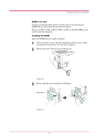
Expansion Memory Installation After removing the side cover, you can see the DIMM socket on top of the main circuit board. DIMM socket Figure A-8 4 Remove the DIMM from its package. 5 Open the clips on both ends of the DIMM socket. Clips Figure A-9 6 Insert the DIMM into the DIMM socket so that the notches on the DIMM align with the corresponding protrusions in the slot. DIMM Figure A-10 A-5
-
 1
1 -
2
-
3
-
4
-
5
-
6
-
7
-
8
-
9
-
10
-
11
-
12
-
13
-
14
-
15
-
16
-
17
-
18
-
19
-
20
-
21
-
22
-
23
-
24
-
25
-
26
-
27
-
28
-
29
-
30
-
31
-
32
-
33
-
34
-
35
-
36
-
37
-
38
-
39
-
40
-
41
-
42
-
43
-
44
-
45
-
46
-
47
-
48
-
49
-
50
-
51
-
52
-
53
-
54
-
55
-
56
-
57
-
58
-
59
-
60
-
61
-
62
-
63
-
 64
64 -
 65
65 -
 66
66 -
 67
67 -
 68
68 -
 69
69 -
 70
70 -
 71
71 -
 72
72 -
 73
73 -
 74
74 -
75
-
76
-
77
-
78
-
79
-
80
-
81
-
82
-
83
-
84
-
85
-
86
-
87
-
88
-
89
-
90
-
91
-
92
-
93
-
94
-
95
-
96
-
97
-
98
 |
 |
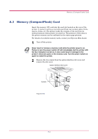
Expansion Memory Installation
A-5
After removing the side cover, you can see the DIMM socket on top of
the main circuit board.
Figure A-8
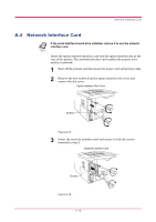
4
Remove the DIMM from its package.
5
Open the clips on both ends of the DIMM socket.
Figure A-9
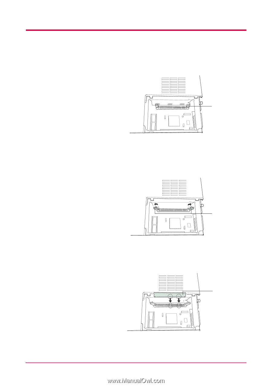
6
Insert the DIMM into the DIMM socket so that the notches on the
DIMM align with the corresponding protrusions in the slot.
Figure A-10
DIMM socket
Clips
DIMM