Kyocera FS 1020D FS-1020D Operation Guide Rev 1.4 - Page 80
B.2 USB Interface, B.2.1 Specifications, B.2.2 Interface Signals, B.2.1
 |
View all Kyocera FS 1020D manuals
Add to My Manuals
Save this manual to your list of manuals |
Page 80 highlights
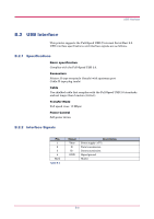
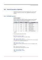
USB Interface B.2 USB Interface This printer supports the Full-Speed USB (Universal Serial Bus) 2.0. USB interface specifications and interface signals are as follows. B.2.1 Specifications Basic specification Complies with the Full-Speed USB 2.0. Connectors Printer: B-type receptacle (female) with upstream port Cable: B-type plug (male) Cable Use shielded cable that complies with the Full-Speed USB 2.0 standards and not longer than 5 meters (16 feet). Transfer Mode Full speed (max. 12 Mbps) Power Control Self-power device B.2.2 Interface Signals Pin 1 2 3 4 Shell Table B-2 Signal Vbus DD+ GND Description Power supply (+5 V) Data transmission Data transmission Signal ground Shield B-6
-
 1
1 -
2
-
3
-
4
-
5
-
6
-
7
-
8
-
9
-
10
-
11
-
12
-
13
-
14
-
15
-
16
-
17
-
18
-
19
-
20
-
21
-
22
-
23
-
24
-
25
-
26
-
27
-
28
-
29
-
30
-
31
-
32
-
33
-
34
-
35
-
36
-
37
-
38
-
39
-
40
-
41
-
42
-
43
-
44
-
45
-
46
-
47
-
48
-
49
-
50
-
51
-
52
-
53
-
54
-
55
-
56
-
57
-
58
-
59
-
60
-
61
-
62
-
63
-
64
-
65
-
66
-
67
-
68
-
69
-
70
-
71
-
72
-
73
-
74
-
 75
75 -
 76
76 -
 77
77 -
 78
78 -
 79
79 -
 80
80 -
 81
81 -
 82
82 -
 83
83 -
 84
84 -
 85
85 -
86
-
87
-
88
-
89
-
90
-
91
-
92
-
93
-
94
-
95
-
96
-
97
-
98
 |
 |
USB Interface
B-6
B.2
USB Interface
This printer supports the Full-Speed USB (Universal Serial Bus) 2.0.
USB interface specifications and interface signals are as follows.
B.2.1
Specifications
Basic specification
Complies with the Full-Speed USB 2.0.
Connectors
Printer: B-type receptacle (female) with upstream port
Cable: B-type plug (male)
Cable
Use shielded cable that complies with the Full-Speed USB 2.0 standards
and not longer than 5 meters (16 feet).
Transfer Mode
Full speed (max. 12 Mbps)
Power Control
Self-power device
B.2.2
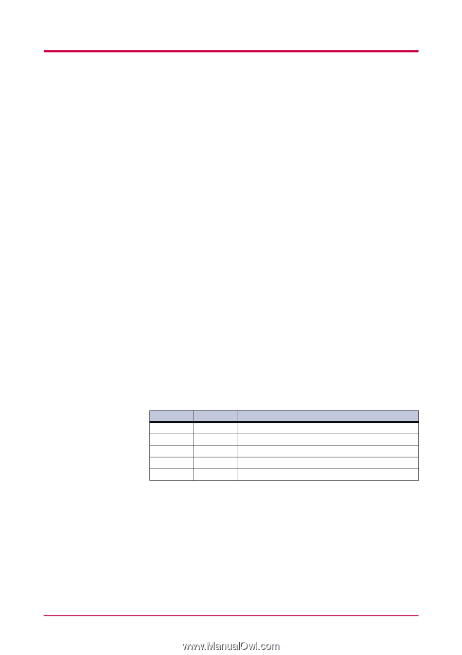
Interface Signals
Pin
Signal
Description
1
Vbus
Power supply (+5 V)
2
D-
Data transmission
3
D+
Data transmission
4
GND
Signal ground
Shell
Shield
Table B-2