Kyocera FS 1020D FS-1020D Operation Guide Rev 1.4 - Page 75
Host Computer Interface
 |
View all Kyocera FS 1020D manuals
Add to My Manuals
Save this manual to your list of manuals |
Page 75 highlights
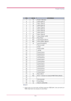
Appendix B Host Computer Interface B This appendix describes the signals used in the laser printer's parallel, USB, and serial (option) interfaces. It also lists pin assignments, signal functions, timings, connector specifications, and voltage levels. For details on the network interface, refer to the IB-21E/IB-22 User's Manual contained on the CD-ROM that is supplied with the printer. This appendix explains the following topics: • Parallel Interface • USB Interface • Serial Interface (Option) • RS-232C Protocol B-1
-
 1
1 -
2
-
3
-
4
-
5
-
6
-
7
-
8
-
9
-
10
-
11
-
12
-
13
-
14
-
15
-
16
-
17
-
18
-
19
-
20
-
21
-
22
-
23
-
24
-
25
-
26
-
27
-
28
-
29
-
30
-
31
-
32
-
33
-
34
-
35
-
36
-
37
-
38
-
39
-
40
-
41
-
42
-
43
-
44
-
45
-
46
-
47
-
48
-
49
-
50
-
51
-
52
-
53
-
54
-
55
-
56
-
57
-
58
-
59
-
60
-
61
-
62
-
63
-
64
-
65
-
66
-
67
-
68
-
69
-
 70
70 -
 71
71 -
 72
72 -
 73
73 -
 74
74 -
 75
75 -
 76
76 -
 77
77 -
 78
78 -
 79
79 -
 80
80 -
81
-
82
-
83
-
84
-
85
-
86
-
87
-
88
-
89
-
90
-
91
-
92
-
93
-
94
-
95
-
96
-
97
-
98
 |
 |

B-1
Appendix B
Host Computer
Interface
B
This appendix describes the signals used in the laser printer’s parallel, USB,
and serial (option) interfaces. It also lists pin assignments, signal functions,
timings, connector specifications, and voltage levels. For details on the
network interface, refer to the IB-21E/IB-22 User’s Manual contained on the
CD-ROM that is supplied with the printer.
This appendix explains the following topics:
•
Parallel Interface
•
USB Interface
•
Serial Interface (Option)
•
RS-232C Protocol