Lenovo J105 Hardware Maintenance Manual - Page 101
Attention
 |
View all Lenovo J105 manuals
Add to My Manuals
Save this manual to your list of manuals |
Page 101 highlights
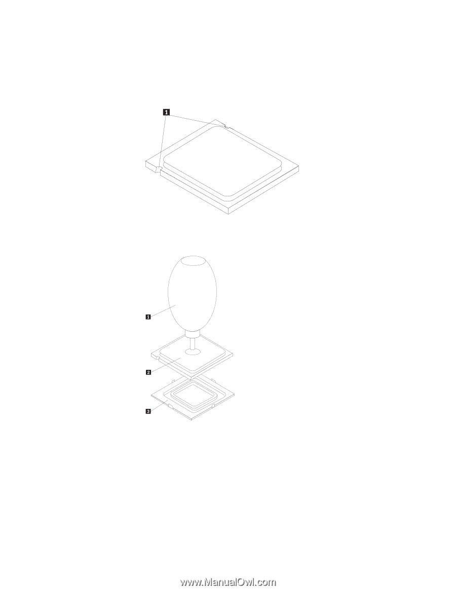
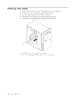
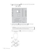
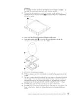
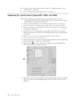
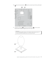
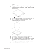
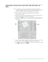
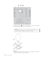
Attention: Be careful to not drop anything onto the microprocessor socket while it is exposed. The socket pins must be kept as clean as possible. 12. To install the microprocessor on the new system board, position the microprocessor so that the notches 1 are aligned with the corresponding tabs in the socket. 13. Make sure that the microprocessor retainer is fully open. 14. Using the vacuum pen 1 to pick up the microprocessor, lower the microprocessor straight down into the socket. 15. Lower the microprocessor retainer. 16. Lock the retainer with the small handle to secure the microprocessor in the socket. 17. The new retention bracket has plastic one-way rings on the posts that insert into the rear of the new system board. Install the new retention bracket by aligning the posts on the module with the holes in the system board and pushing the posts through the holes until the retention bracket is secure. 18. Install the heat sink and fan assembly on the new system board. 19. Install the new system board into the chassis and align the screw holes with those in the chassis. Insert and tighten the screws that secure the system board. Chapter 8. Replacing FRUs (Types 8252, 8253, 8254, 8255, 8256, 8257, 8258, and 8259) 95
-
 1
1 -
2
-
3
-
4
-
5
-
6
-
7
-
8
-
9
-
10
-
11
-
12
-
13
-
14
-
15
-
16
-
17
-
18
-
19
-
20
-
21
-
22
-
23
-
24
-
25
-
26
-
27
-
28
-
29
-
30
-
31
-
32
-
33
-
34
-
35
-
36
-
37
-
38
-
39
-
40
-
41
-
42
-
43
-
44
-
45
-
46
-
47
-
48
-
49
-
50
-
51
-
52
-
53
-
54
-
55
-
56
-
57
-
58
-
59
-
60
-
61
-
62
-
63
-
64
-
65
-
66
-
67
-
68
-
69
-
70
-
71
-
72
-
73
-
74
-
75
-
76
-
77
-
78
-
79
-
80
-
81
-
82
-
83
-
84
-
85
-
86
-
87
-
88
-
89
-
90
-
91
-
92
-
93
-
94
-
95
-
 96
96 -
 97
97 -
 98
98 -
 99
99 -
 100
100 -
 101
101 -
 102
102 -
 103
103 -
 104
104 -
 105
105 -
 106
106 -
107
-
108
-
109
-
110
-
111
-
112
-
113
-
114
-
115
-
116
-
117
-
118
-
119
-
120
-
121
-
122
-
123
-
124
-
125
-
126
-
127
-
128
-
129
-
130
-
131
-
132
-
133
-
134
-
135
-
136
-
137
-
138
-
139
-
140
-
141
-
142
-
143
-
144
-
145
-
146
-
147
-
148
-
149
-
150
-
151
-
152
-
153
-
154
-
155
-
156
-
157
-
158
-
159
-
160
-
161
-
162
-
163
-
164
-
165
-
166
-
167
-
168
-
169
-
170
-
171
-
172
-
173
-
174
-
175
-
176
-
177
-
178
-
179
-
180
-
181
-
182
-
183
-
184
-
185
-
186
-
187
-
188
-
189
-
190
-
191
-
192
-
193
-
194
-
195
-
196
-
197
-
198
-
199
-
200
-
201
-
202
-
203
-
204
-
205
-
206
-
207
-
208
-
209
-
210
-
211
-
212
-
213
-
214
-
215
-
216
-
217
-
218
 |
 |