Lenovo J105 Hardware Maintenance Manual - Page 88
connectors, Removing, covers
 |
View all Lenovo J105 manuals
Add to My Manuals
Save this manual to your list of manuals |
Page 88 highlights
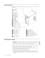
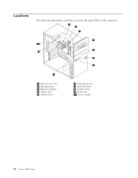
Rear connectors The following illustration shows the locations of the connectors on the rear of the computer. 1 Power connector 2 Voltage selection switch 3 Mouse connector 4 Keyboard connector 5 Serial connector 6 Parallel connector 7 VGA monitor connector 8 USB connectors 9 Ethernet connector 10 USB connectors 11 Microphone connector 12 Audio line out connector 13 Audio line in connector 14 AGP or PCI Express x16 graphics adapter connector (some models) 15 PCI adapter slots Removing the covers Important Read Chapter 2, "Safety information," on page 3 and "Handling electrostatic discharge-sensitive devices" on page 6 before opening the cover. Some FRU replacements require the removal of only the left-side cover. Others require removal of both the left-side and the right-side covers. 1. Shut down the operating system, remove any media (DVDs, CDs, or tapes) from the drives, and turn off all attached devices. 2. Unplug all power cords from electrical outlets. 3. Disconnect all cables attached to the computer. This includes power cords, input/output (I/O) cables, and any other cables that are connected to the computer. 82 Lenovo 3000 J Series
-
 1
1 -
2
-
3
-
4
-
5
-
6
-
7
-
8
-
9
-
10
-
11
-
12
-
13
-
14
-
15
-
16
-
17
-
18
-
19
-
20
-
21
-
22
-
23
-
24
-
25
-
26
-
27
-
28
-
29
-
30
-
31
-
32
-
33
-
34
-
35
-
36
-
37
-
38
-
39
-
40
-
41
-
42
-
43
-
44
-
45
-
46
-
47
-
48
-
49
-
50
-
51
-
52
-
53
-
54
-
55
-
56
-
57
-
58
-
59
-
60
-
61
-
62
-
63
-
64
-
65
-
66
-
67
-
68
-
69
-
70
-
71
-
72
-
73
-
74
-
75
-
76
-
77
-
78
-
79
-
80
-
81
-
82
-
 83
83 -
 84
84 -
 85
85 -
 86
86 -
 87
87 -
 88
88 -
 89
89 -
 90
90 -
 91
91 -
 92
92 -
 93
93 -
94
-
95
-
96
-
97
-
98
-
99
-
100
-
101
-
102
-
103
-
104
-
105
-
106
-
107
-
108
-
109
-
110
-
111
-
112
-
113
-
114
-
115
-
116
-
117
-
118
-
119
-
120
-
121
-
122
-
123
-
124
-
125
-
126
-
127
-
128
-
129
-
130
-
131
-
132
-
133
-
134
-
135
-
136
-
137
-
138
-
139
-
140
-
141
-
142
-
143
-
144
-
145
-
146
-
147
-
148
-
149
-
150
-
151
-
152
-
153
-
154
-
155
-
156
-
157
-
158
-
159
-
160
-
161
-
162
-
163
-
164
-
165
-
166
-
167
-
168
-
169
-
170
-
171
-
172
-
173
-
174
-
175
-
176
-
177
-
178
-
179
-
180
-
181
-
182
-
183
-
184
-
185
-
186
-
187
-
188
-
189
-
190
-
191
-
192
-
193
-
194
-
195
-
196
-
197
-
198
-
199
-
200
-
201
-
202
-
203
-
204
-
205
-
206
-
207
-
208
-
209
-
210
-
211
-
212
-
213
-
214
-
215
-
216
-
217
-
218
 |
 |
