Lenovo J105 Hardware Maintenance Manual - Page 135
connections
 |
View all Lenovo J105 manuals
Add to My Manuals
Save this manual to your list of manuals |
Page 135 highlights
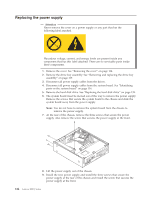
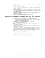
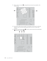
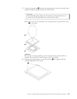
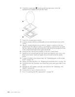
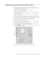
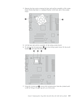
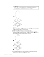
Replacing the system board (Types 8458, 8459, and 8460) Note: When replacing the system board, a new retention bracket for the microprocessor heat sink is required. Make sure you have a new retention bracket before beginning this procedure. 1. Remove the cover. See "Removing the cover" on page 114. 2. Lift the fan duct off the heat sink fan. 3. Remove any adapter cards installed in the PCI connectors. See "Replacing a PCI adapter" on page 121. 4. Remove the drive bay assembly. See "Removing and replacing the drive bay assembly" on page 119. 5. Take note of the location of all cable connections on the system board and disconnect all cables. See "Identifying parts on the system board" on page 116. 6. Remove the hard disk drive. See "Replacing the hard disk drive" on page 139. 7. Remove the screws that secure the system board to the chassis. 8. Lift the system board out of the chassis. 9. Remove the memory modules from the failing system board and install them in the same location on the new system board. 10. Disconnect the heat sink and fan assembly cable from the system board. See "Identifying parts on the system board" on page 116. 11. Rotate handle 1 to release the heat sink clamp and then disengage the clamp from the plastic retention bracket. 12. Lift the heat sink and fan assembly off the failing system board. Chapter 9. Replacing FRUs (Types 8453, 8454, 8455, 8456, 8457, 8458, 8459, and 8460) 129
-
 1
1 -
2
-
3
-
4
-
5
-
6
-
7
-
8
-
9
-
10
-
11
-
12
-
13
-
14
-
15
-
16
-
17
-
18
-
19
-
20
-
21
-
22
-
23
-
24
-
25
-
26
-
27
-
28
-
29
-
30
-
31
-
32
-
33
-
34
-
35
-
36
-
37
-
38
-
39
-
40
-
41
-
42
-
43
-
44
-
45
-
46
-
47
-
48
-
49
-
50
-
51
-
52
-
53
-
54
-
55
-
56
-
57
-
58
-
59
-
60
-
61
-
62
-
63
-
64
-
65
-
66
-
67
-
68
-
69
-
70
-
71
-
72
-
73
-
74
-
75
-
76
-
77
-
78
-
79
-
80
-
81
-
82
-
83
-
84
-
85
-
86
-
87
-
88
-
89
-
90
-
91
-
92
-
93
-
94
-
95
-
96
-
97
-
98
-
99
-
100
-
101
-
102
-
103
-
104
-
105
-
106
-
107
-
108
-
109
-
110
-
111
-
112
-
113
-
114
-
115
-
116
-
117
-
118
-
119
-
120
-
121
-
122
-
123
-
124
-
125
-
126
-
127
-
128
-
129
-
 130
130 -
 131
131 -
 132
132 -
 133
133 -
 134
134 -
 135
135 -
 136
136 -
 137
137 -
 138
138 -
 139
139 -
 140
140 -
141
-
142
-
143
-
144
-
145
-
146
-
147
-
148
-
149
-
150
-
151
-
152
-
153
-
154
-
155
-
156
-
157
-
158
-
159
-
160
-
161
-
162
-
163
-
164
-
165
-
166
-
167
-
168
-
169
-
170
-
171
-
172
-
173
-
174
-
175
-
176
-
177
-
178
-
179
-
180
-
181
-
182
-
183
-
184
-
185
-
186
-
187
-
188
-
189
-
190
-
191
-
192
-
193
-
194
-
195
-
196
-
197
-
198
-
199
-
200
-
201
-
202
-
203
-
204
-
205
-
206
-
207
-
208
-
209
-
210
-
211
-
212
-
213
-
214
-
215
-
216
-
217
-
218
 |
 |
