Lenovo J105 Hardware Maintenance Manual - Page 130
components.
 |
View all Lenovo J105 manuals
Add to My Manuals
Save this manual to your list of manuals |
Page 130 highlights
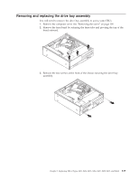
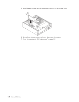
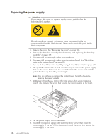
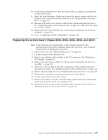
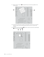
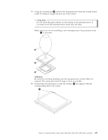
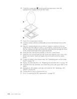
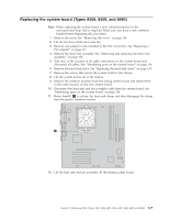
Replacing the power supply Attention Never remove the cover on a power supply or any part that has the following label attached. Hazardous voltage, current, and energy levels are present inside any component that has this label attached. There are no servicable parts inside these components. 1. Remove the cover. See "Removing the cover" on page 114. 2. Remove the drive bay assembly. See "Removing and replacing the drive bay assembly" on page 119. 3. Disconnect all power supply cables from the drives. 4. Disconnect all power supply cables from the system board. See "Identifying parts on the system board" on page 116. 5. Remove the hard disk drive. See "Replacing the hard disk drive" on page 139. 6. The system board must be moved out of the way to remove the power supply. Remove the screws that secure the system board to the chassis and slide the system board away from the power supply. Note: You do not have to remove the system board from the chassis to remove the power supply. 7. At the rear of the chassis, remove the three screws that secure the power supply. Also remove the screw that secures the power supply at the front. 8. Lift the power supply out of the chassis. 9. Install the new power supply and install the three screws that secure the power supply at the rear of the chassis and install the screw that secures the power supply at the front. 124 Lenovo 3000 J Series
-
 1
1 -
2
-
3
-
4
-
5
-
6
-
7
-
8
-
9
-
10
-
11
-
12
-
13
-
14
-
15
-
16
-
17
-
18
-
19
-
20
-
21
-
22
-
23
-
24
-
25
-
26
-
27
-
28
-
29
-
30
-
31
-
32
-
33
-
34
-
35
-
36
-
37
-
38
-
39
-
40
-
41
-
42
-
43
-
44
-
45
-
46
-
47
-
48
-
49
-
50
-
51
-
52
-
53
-
54
-
55
-
56
-
57
-
58
-
59
-
60
-
61
-
62
-
63
-
64
-
65
-
66
-
67
-
68
-
69
-
70
-
71
-
72
-
73
-
74
-
75
-
76
-
77
-
78
-
79
-
80
-
81
-
82
-
83
-
84
-
85
-
86
-
87
-
88
-
89
-
90
-
91
-
92
-
93
-
94
-
95
-
96
-
97
-
98
-
99
-
100
-
101
-
102
-
103
-
104
-
105
-
106
-
107
-
108
-
109
-
110
-
111
-
112
-
113
-
114
-
115
-
116
-
117
-
118
-
119
-
120
-
121
-
122
-
123
-
124
-
 125
125 -
 126
126 -
 127
127 -
 128
128 -
 129
129 -
 130
130 -
 131
131 -
 132
132 -
 133
133 -
 134
134 -
 135
135 -
136
-
137
-
138
-
139
-
140
-
141
-
142
-
143
-
144
-
145
-
146
-
147
-
148
-
149
-
150
-
151
-
152
-
153
-
154
-
155
-
156
-
157
-
158
-
159
-
160
-
161
-
162
-
163
-
164
-
165
-
166
-
167
-
168
-
169
-
170
-
171
-
172
-
173
-
174
-
175
-
176
-
177
-
178
-
179
-
180
-
181
-
182
-
183
-
184
-
185
-
186
-
187
-
188
-
189
-
190
-
191
-
192
-
193
-
194
-
195
-
196
-
197
-
198
-
199
-
200
-
201
-
202
-
203
-
204
-
205
-
206
-
207
-
208
-
209
-
210
-
211
-
212
-
213
-
214
-
215
-
216
-
217
-
218
 |
 |
