Lenovo J105 Hardware Maintenance Manual - Page 95
Identifying
 |
View all Lenovo J105 manuals
Add to My Manuals
Save this manual to your list of manuals |
Page 95 highlights
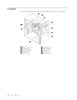
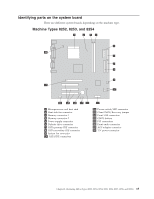
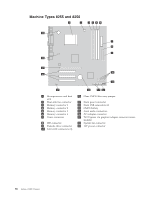
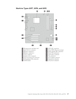
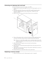
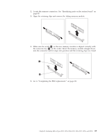
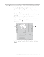
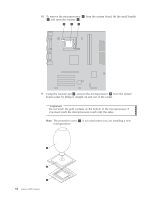
2. Locate the memory connectors. See "Identifying parts on the system board" on page 85. 3. Open the retaining clips and remove the failing memory module. 4. Make sure the notch 1 on the new memory module is aligned correctly with the connector key 2 on the socket. Insert the memory module straight down into the connector until it snaps into position and the retaining clips are closed. 5. Go to "Completing the FRU replacement." on page 111. Chapter 8. Replacing FRUs (Types 8252, 8253, 8254, 8255, 8256, 8257, 8258, and 8259) 89
-
 1
1 -
2
-
3
-
4
-
5
-
6
-
7
-
8
-
9
-
10
-
11
-
12
-
13
-
14
-
15
-
16
-
17
-
18
-
19
-
20
-
21
-
22
-
23
-
24
-
25
-
26
-
27
-
28
-
29
-
30
-
31
-
32
-
33
-
34
-
35
-
36
-
37
-
38
-
39
-
40
-
41
-
42
-
43
-
44
-
45
-
46
-
47
-
48
-
49
-
50
-
51
-
52
-
53
-
54
-
55
-
56
-
57
-
58
-
59
-
60
-
61
-
62
-
63
-
64
-
65
-
66
-
67
-
68
-
69
-
70
-
71
-
72
-
73
-
74
-
75
-
76
-
77
-
78
-
79
-
80
-
81
-
82
-
83
-
84
-
85
-
86
-
87
-
88
-
89
-
 90
90 -
 91
91 -
 92
92 -
 93
93 -
 94
94 -
 95
95 -
 96
96 -
 97
97 -
 98
98 -
 99
99 -
 100
100 -
101
-
102
-
103
-
104
-
105
-
106
-
107
-
108
-
109
-
110
-
111
-
112
-
113
-
114
-
115
-
116
-
117
-
118
-
119
-
120
-
121
-
122
-
123
-
124
-
125
-
126
-
127
-
128
-
129
-
130
-
131
-
132
-
133
-
134
-
135
-
136
-
137
-
138
-
139
-
140
-
141
-
142
-
143
-
144
-
145
-
146
-
147
-
148
-
149
-
150
-
151
-
152
-
153
-
154
-
155
-
156
-
157
-
158
-
159
-
160
-
161
-
162
-
163
-
164
-
165
-
166
-
167
-
168
-
169
-
170
-
171
-
172
-
173
-
174
-
175
-
176
-
177
-
178
-
179
-
180
-
181
-
182
-
183
-
184
-
185
-
186
-
187
-
188
-
189
-
190
-
191
-
192
-
193
-
194
-
195
-
196
-
197
-
198
-
199
-
200
-
201
-
202
-
203
-
204
-
205
-
206
-
207
-
208
-
209
-
210
-
211
-
212
-
213
-
214
-
215
-
216
-
217
-
218
 |
 |

2.
Locate
the
memory
connectors.
See
“Identifying
parts
on
the
system
board”
on
page
85.
3.
Open
the
retaining
clips
and
remove
the
failing
memory
module.
4.
Make
sure
the
notch
±1²
on
the
new
memory
module
is
aligned
correctly
with
the
connector
key
±2²
on
the
socket.
Insert
the
memory
module
straight
down
into
the
connector
until
it
snaps
into
position
and
the
retaining
clips
are
closed.
5.
Go
to
“Completing
the
FRU
replacement.”
on
page
111.
Chapter
8.
Replacing
FRUs
(Types
8252,
8253,
8254,
8255,
8256,
8257,
8258,
and
8259)
89